Optical communication module

a communication module and optical technology, applied in electromagnetic transceivers, instruments, electric digital data processing, etc., can solve the problems of imposing restrictions on the design of additional functions, and achieve the effect of reducing the limited number of pins included and effectively using an excess number of pins

Inactive Publication Date: 2006-03-30
MITSUBISHI ELECTRIC CORP
View PDF6 Cites 21 Cited by
  • Summary
  • Abstract
  • Description
  • Claims
  • Application Information

AI Technical Summary

Benefits of technology

[0013] The module in accordance with the present invention can perform writing of NVR data into either the EEPROM or fresh memory of the microcomputer, and updating and erasing of the NVR data by using the second serial bus which is a dedicated serial bus used for transmission of other management data, thereby avoiding the necessity for additionally installing a serial bus for writing NVR data into the optical communication module in the exterior of the optical communication module, and hence reducing the limited number of pins included in the optical communication module. Therefore, the present invention offers an advantage of being able to effectively use an excess number of pins for other additional functions.

Problems solved by technology

As a result, restrictions are imposed on the design of an additional function which newly requires a number of pins.

Method used


Image

  • Optical communication module
  • Optical communication module

Examples


embodiment 1

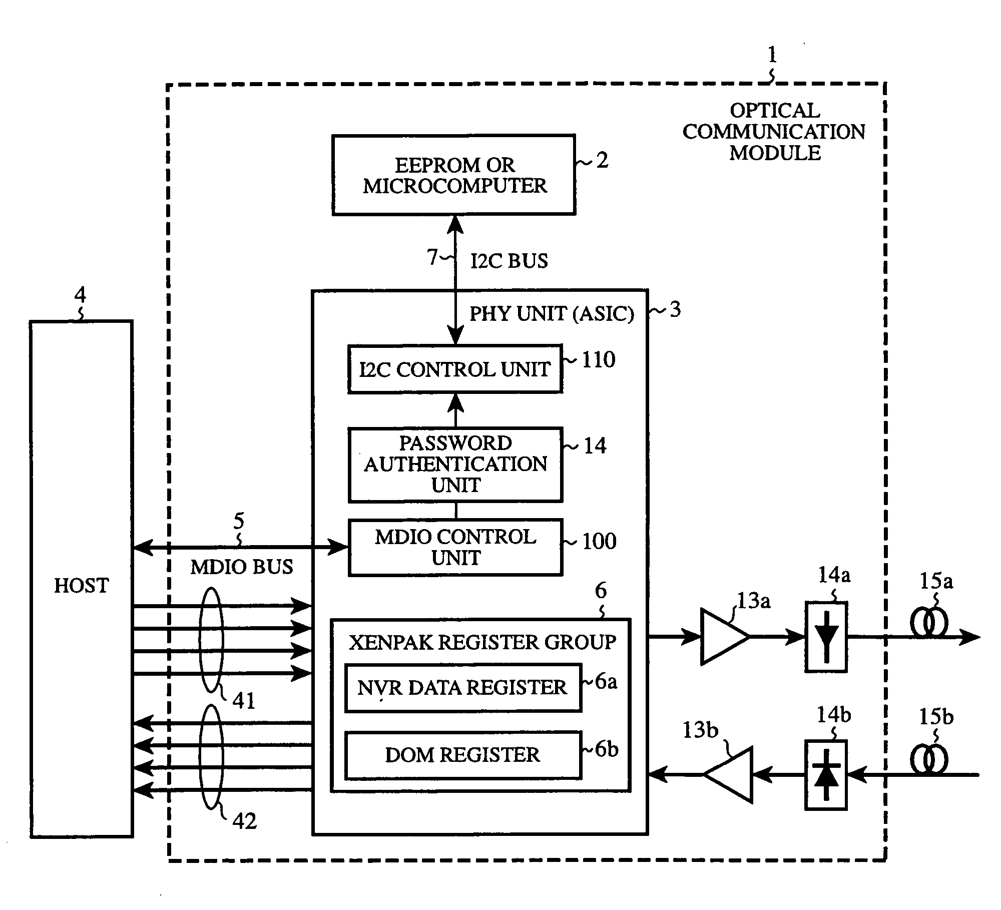
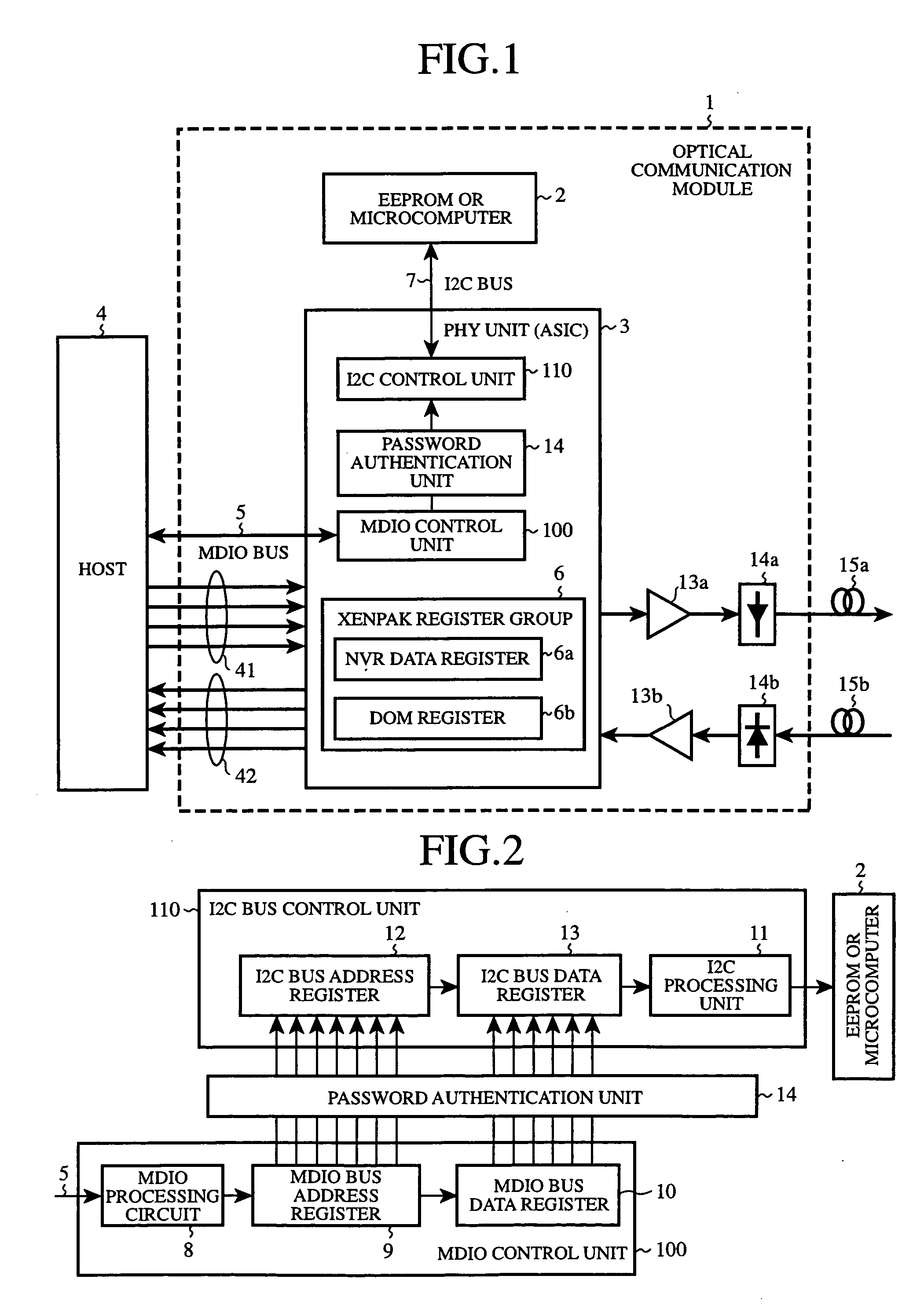
[0017]FIG. 1 is a block diagram schematically showing the structure of an optical communication module in accordance with embodiment 1 of the present invention. Hereafter, part of the optical communication module associated with the present invention will be explained mainly.

[0018] The optical communication module 1 is so constructed as to be compliant with specifications, such as above-mentioned XENPAK, XPAK, X2, or XFP. The optical communication module 1 is provided with a 10 Gbps-capable PHY unit (i.e., a physical-layer unit) 3 which consists of an ASIC and has a communication function, an EEPROM or a microcomputer 2 having a flash memory, and an operation function and peripheral functions, a laser light emitting element 14a, a light receiving element 14b, a driver 13a, an input amplifier 13b, etc. A main function of the microcomputer, which is not a subject of the present invention, is to keep the output of the laser light emitting element 14a constant, and to monitor the statu...


PUM


Abstract

An optical communication module includes a physical-layer unit having a first control unit for receiving a write destination address and NVR data from a host via a serial bus, and for carrying out serial/parallel conversion of the received write destination address and NVR data, and storing them in registers of the first control unit, respectively, and a second control unit for copying the stored write destination address and NVR data to corresponding registers of the second control unit, respectively, and for carrying out parallel/serial conversion of the write destination address and NVR data which are copied to the registers of the second control unit, respectively, and sending them to either an EEPROM or a flash memory of a microcomputer, as well as a write command, via another serial bus to write the NVR data into either the EEPROM or the flash memory of the microcomputer.

Description

BACKGROUND OF THE INVENTION [0001] 1. Field of the Invention [0002] The present invention relates to an optical communication module which carries out high-speed transmission by using an optical transmission technology and which is applied to, for example, 10 Gbps Ethernet (registered trademark). More particularly, it relates to a technology for writing NVR data which is used for initial setting into either an EEPROM or a flash memory of a microcomputer in advance. [0003] 2. Description of Related Art [0004] In recent years, high-speed high-capacity optical networks have been constructed in order to respond to increase in the information-carrying capacity of the Internet which is caused by the spread of the Internet. As standards for communication equipment for use in high-speed high-capacity optical networks, there has been provided the IEEE802.3ae standard which is a next-generation Ethernet (registered trademark) standard which is aimed to increase the information-carrying capaci...

Claims


Application Information

Patent Timeline
Patent Type & Authority Applications(United States)
IPC IPC(8): G06F13/38H04B10/40H04B10/50H04B10/524H04B10/54H04B10/60
CPCG06F13/385
Inventor MORIWAKI, SHOHEIAZEKAWA, YOSHIFUMICHIBA, OSAMU
Owner MITSUBISHI ELECTRIC CORP
Why Eureka
Try Eureka