Optical module and optical line terminal device

A technology of optical line terminals and optical modules, which is applied in the field of optical modules, can solve the problems of large area of ​​system boards, large volume of optical modules, and small number of optical modules, etc., to expand system capacity, reduce the number of pins, and upgrade boards effect of density

Inactive Publication Date: 2016-10-26
HISENSE BROADBAND MULTIMEDIA TECH
View PDF5 Cites 23 Cited by
  • Summary
  • Abstract
  • Description
  • Claims
  • Application Information

AI Technical Summary

Problems solved by technology

[0004] In order to solve the problem that the existing optical module has a large volume and occupies a large area of ​​the system board, resulting in a small number of optical modules that can be connected to the current system board, a type of optical module and an optical line terminal device are proposed, which can solve the above problems

Method used


Image

  • Optical module and optical line terminal device
  • Optical module and optical line terminal device
  • Optical module and optical line terminal device

Examples


Embodiment 1

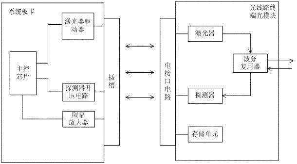
[0023] This embodiment proposes an optical module, such as figure 1 As shown, including: housing, circuit board, optical component, and storage unit,

[0024] The optical component and the storage unit are respectively electrically connected to the circuit board;

[0025] The optical component is used to generate the downstream optical signal of the corresponding rate and wavelength according to the electrical signal; or is used to receive the upstream optical signal of the corresponding rate and wavelength in the burst mode, and convert the upstream optical signal into an electrical signal;

[0026] The storage unit is used to store the working parameters of the optical component;

[0027] The optical component and the storage unit are encapsulated in a housing (not shown in the figure). The circuit board has an electrical interface. The electrical interface has a transmitting ground, a receiving ground, a power supply terminal, a drive terminal of the optical component, and a storage...

Embodiment 2

[0035] The present invention proposes an optical line terminal device based on the optical module in the first embodiment, such as figure 1 As shown, it includes a system board and an optical module. The system board is provided with a number of slots. The optical module is pluggable and connected to the matching slot through an electrical interface. The system board is provided with a one-to-one correspondence with the slot The connected optical module control circuit, the optical module control circuit includes at least a main control chip and a driving circuit, and the optical module includes an optical component and a storage unit,

[0036] The optical component is used to generate the downstream optical signal of the corresponding rate and wavelength according to the electrical signal; or is used to receive the upstream optical signal of the corresponding rate and wavelength in the burst mode, and convert the upstream optical signal into an electrical signal;

[0037] The stora...

Embodiment 3

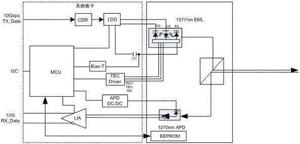
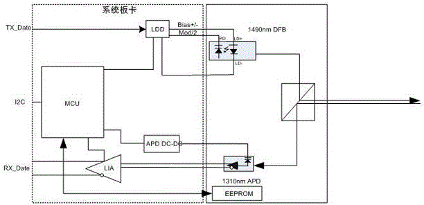
[0045] When the optical component includes a detector, this embodiment will take the distributed feedback laser DFB as an example for further explanation, such as image 3 As shown, the distributed feedback laser DFB includes a laser emitting diode LD and a backlight detector PD. The laser driver LDD is connected to the laser emitting diode through the laser emitting diode bias pins (LD+, LD-) of the electrical interface. The backlight detector pin is connected to the backlight detector PD. The principle that the laser is a DFB laser is simpler. The modulation signal sent by the laser driver LDD is loaded on the LD of the DFB laser through the bias pin (LD+, LD-) in the form of Bias±Mod / 2, and passes through the backlight detector pin It forms an APC loop with PD, and the number of interface circuit pins can be reduced to 10, which can further reduce the volume of the optical module and increase the number of pluggable optical modules in the system.

[0046] The connection mode ...


PUM


Abstract

The invention discloses an optical module and an optical line terminal device. The optical module includes: a housing, a circuit board, an optical assembly and a storage unit. The optical assembly is in electrical connection to the circuit board and is intended for generating an optical signal based on an electrical signal; or is intended for converting the received optical signal to an electrical signal; the storage unit is in electrical connection to the circuit board, and is intended for storing the working parameters of the optical assembly; the circuit board, the optical assembly and the storage unit are packaged inside the housing, and the circuit board is provided with an electrical interface thereon, and the electrical interface have pins which are in one by one corresponding connection to a driving end of the optical assembly and a data transmission base pin of the storage unit. When the optical module works, the working parameters of the optical assembly are transmitted to an external master control chip through the electrical interface, and the external master control chip configures an external drive circuit on the basis of the working parameters of the optical assembly, and the external drive circuit drives the optical assembly through the electrical interface. The optical module only packages the optical assembly and the storage unit and is conductive to the reduction of the volume of the optical module.

Description

Technical field [0001] The invention belongs to the technical field of optical fiber communication, and specifically relates to an optical module. Background technique [0002] In the optical fiber communication system, the OLT (Optical Line Terminator, optical line terminal) is usually set in the central office of the access network system of the optical fiber communication system. The OLT is responsible for converting the electrical signal data in the switch into optical signal data for sending out, and receiving external The transmitted optical signals are converted into electrical signals and sent to the switch. [0003] Such as figure 1 As shown, taking a traditional 10G PON OLT optical module as an example, it is mainly composed of the following parts: electro-absorption external modulation laser EML, laser driver LDD, clock recovery unit CDR, thermoelectric cooling control (TEC) driver, electro-absorption bias circuit Bias-T; detector APD, limiting amplifier LIA, APD boost ...

Claims


Application Information

Patent Timeline
Patent Type & Authority Applications(China)
IPC IPC(8): H04B10/40G02B6/42
CPCG02B6/42H04B10/40H04B10/25G02B6/428H04B10/27H04B10/503H04B10/801
Inventor 张强赵其圣
Owner HISENSE BROADBAND MULTIMEDIA TECH
Why Eureka
Try Eureka