Multilayer pillbox type parallel-plate waveguide antenna and corresponding antenna system

a waveguide antenna and pillbox technology, applied in the direction of slot antennas, linear waveguide fed arrays, antennas, etc., can solve the problems of large size of the complete antenna system, low modularity, and inability to reduce the overall size of the antenna, so as to improve the transfer of energy between two successive layers, reduce the resonance effects that appear in a continuous slot, and optimize the yield

Active Publication Date: 2016-01-26
UNIV DE RENNES I +1
View PDF13 Cites 4 Cited by
  • Summary
  • Abstract
  • Description
  • Claims
  • Application Information

AI Technical Summary

Benefits of technology

[0048]Thus, the resonance effects that appear in a continuous slot are reduced. The transfer of energy between two successive layers is thereby improved in a wide angular range and over a wide frequency band. In other words, an antenna is obtained showing optimized yield in terms of power transfer.
[0076]Thus, it is possible to carry out a 3D reconfiguration (beam-shape changing and / or beam steering) in a way that is simple, reliable, compact and low-cost.

Problems solved by technology

These solutions are very attractive but remain bulky.
One major drawback of this second technique is the large size of the complete antenna system and its low modularity because all the parts (the feeding part, the guiding part and the radiating part) are made on one and the same substrate.
Also, the Rotman lens has large dimensions which mean that the overall size of the antenna cannot be reduced.
This structure is also limited in terms of number of input beams to achieve full beam-steering.
Finally, such a structure shows high insertion losses.
The main drawbacks of this third known technique lie in the fact that the means of transition comprise a single slot, which does not enable an optimal transfer of energy (owing to the existence of resonance phenomena in a single slot) and is efficient only in a narrow angular range.
The resolution is therefore not optimal.
Furthermore, the combined use (in the means of transition) of a parabolic reflector and a single slot do not make it possible, according to the document WO91 / 17586, to obtain a perfectly plane wavefront in the top layer (after reflection on the reflector) if the impinging wavefront of the bottom layer is a cylindrical wavefront (or more generally not plane).
Furthermore, this third known technique does not enable the use of several excitation sources since the horn extends directly up to the edge of the parabolic reflector (sectoral horn).
No beam reconfiguration or beam steering is therefore possible.
One drawback of this fourth known technique is that it can work with only one polarization (horizontal polarization: the TE mode in parallel-plate waveguide or PPW).
It therefore cannot work in double polarization.
Furthermore, like the third known technique, it does not enable the use of several excitation sources.
No beam reconfiguration is therefore possible.
Another drawback of the fourth known technique is that the increase in efficiency of the transition is done at the cost of an increase of the coupling region (the number and size of the circular apertures included in the triangular mesh) and therefore ultimately an increase in the space requirement and cost of the antenna.

Method used


Image

  • Multilayer pillbox type parallel-plate waveguide antenna and corresponding antenna system
  • Multilayer pillbox type parallel-plate waveguide antenna and corresponding antenna system
  • Multilayer pillbox type parallel-plate waveguide antenna and corresponding antenna system

Examples


Embodiment Construction

[0094]We shall strive more particularly here below in the document to describe the problems and issues existing in the field of antennas for latest-generation automobile radars that the inventors of the present patent application have faced. The invention is of course not restricted to this particular field of application but is of value for any technique that has to cope with a proximate or similar set of problems and issues.

[0095]It must also be noted that, in all the figures of the present document, the identical elements are designated by same numerical references.

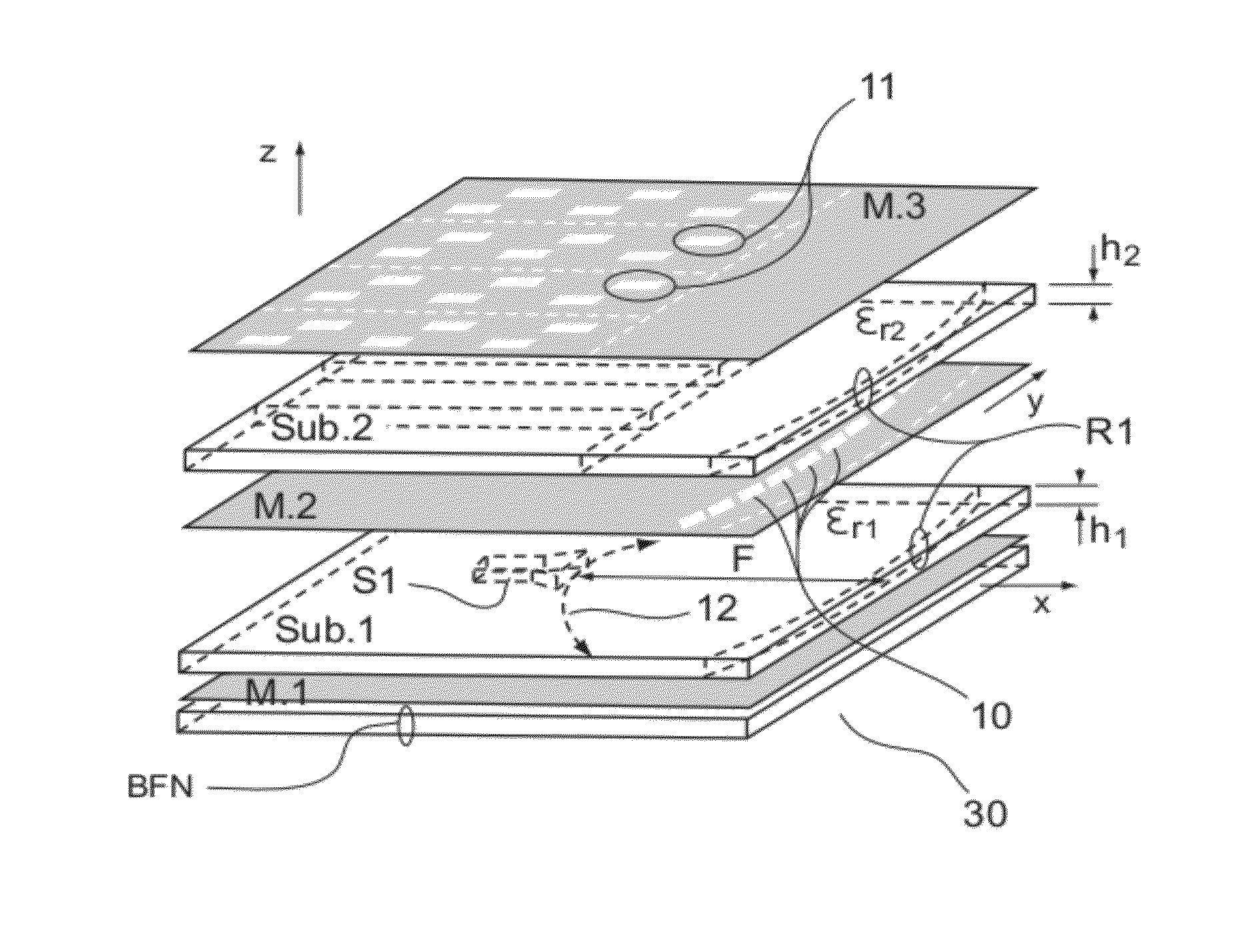
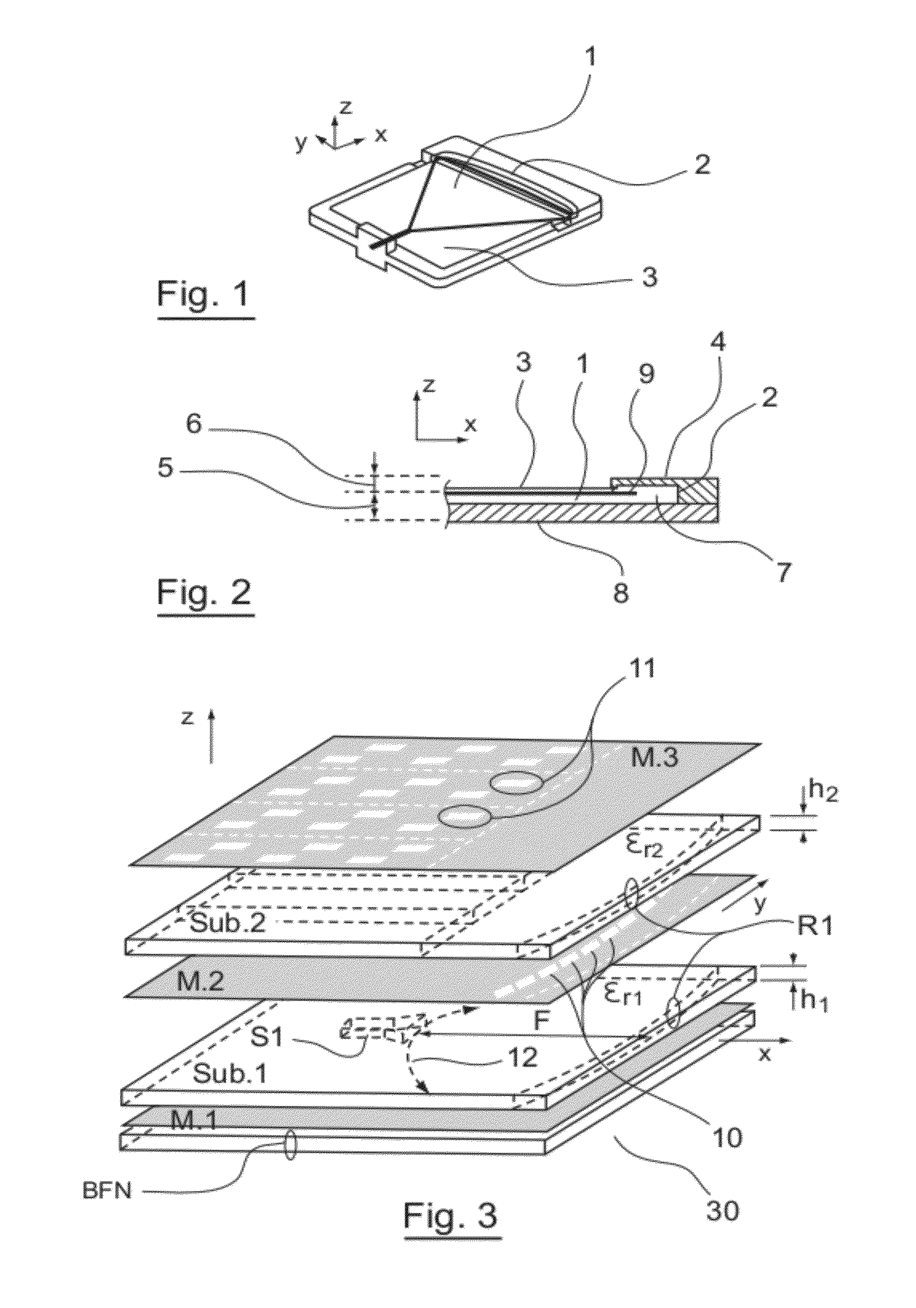
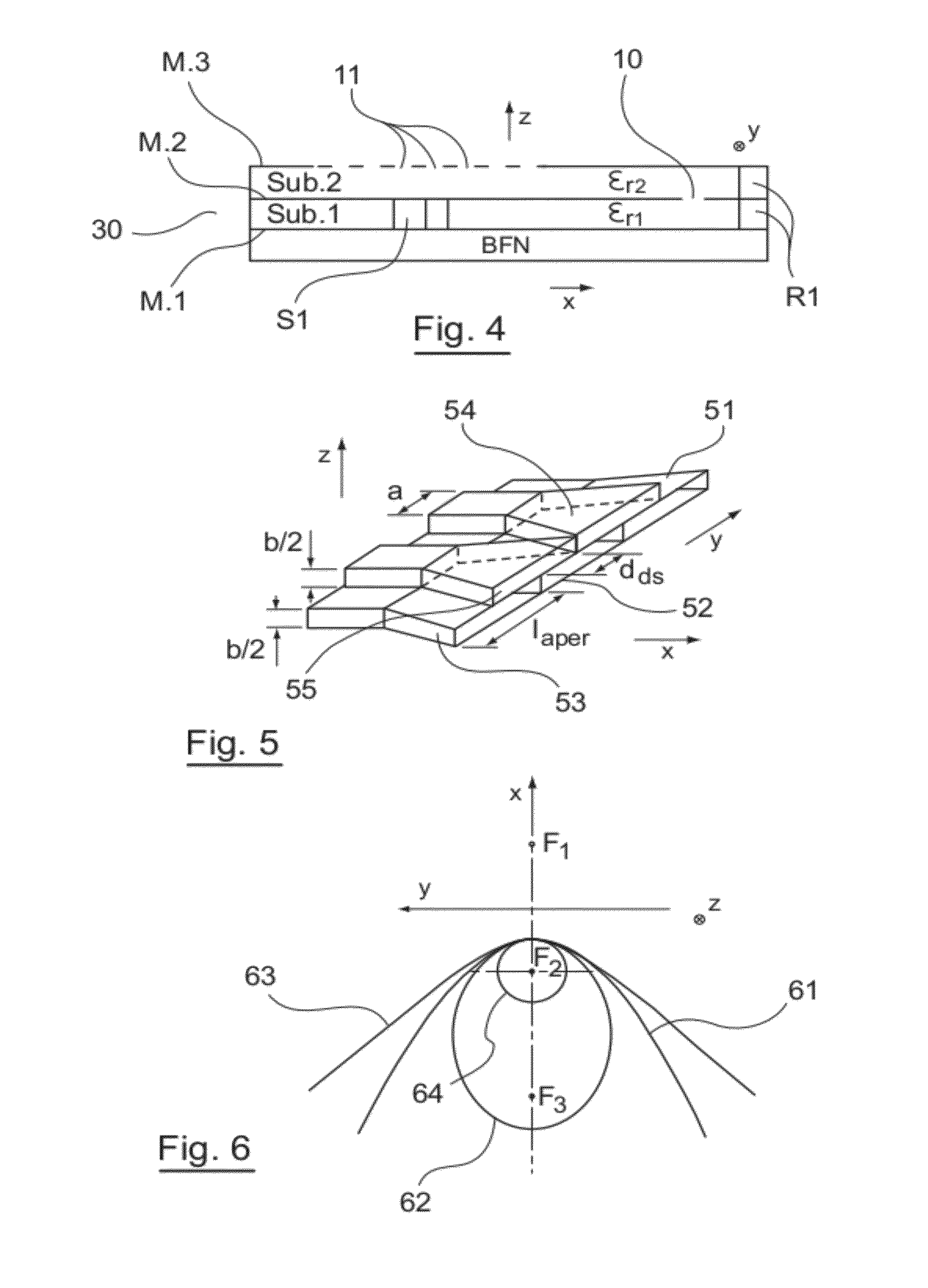
[0096]Referring now to FIGS. 3 and 4, we present a two-layer antenna 30 according to one particular embodiment of the invention. Such an antenna may be used for example in radars for automobile applications.

[0097]In this embodiment, the antenna 30 has a guiding part with two parallel-plate layers having a metal plate M.2 in common. More specifically, the guiding part comprises:[0098]a first parallel-plate layer itself ...


PUM


Abstract

A multilayer antenna is provided, which includes a power supply portion generating a wave, a radiating portion, and a guide portion that makes it possible to guide the wave from the power supply portion to the radiating portion. The guide portion includes: at least two stacked guide layers having parallel planes and, for each pair of adjacent layers, a transition between the adjacent layers, including a reflector engaging with a slot-coupling. For at least one pair of adjacent layers, for which the guide portion includes a non-planar reflector, the slot-coupling includes a plurality of slots. Each slot includes a main body that is elongate along at least one axis. The slots are placed on at least one row and together form a pattern that extends along the reflector and has a shape that is dependent on the shape of the reflector.

Description

CROSS-REFERENCE TO RELATED APPLICATIONS[0001]This Application is a Section 371 National Stage Application of International Application No. PCT / EP2010 / 054060, filed Mar. 29, 2010 and published as WO 2010 / 112443 on Oct. 7, 2010, not in English.STATEMENT REGARDING FEDERALLY SPONSORED RESEARCH OR DEVELOPMENT[0002]None.THE NAMES OF PARTIES TO A JOINT RESEARCH AGREEMENT[0003]None.FIELD OF THE DISCLOSURE[0004]The field of the disclosure is that of multilayer parallel-plate waveguide antennas also called pillbox antennas or cheese antennas.[0005]The disclosure has numerous applications, for example in:[0006]automobiles radars,[0007]communications between mobile platforms (cars, trucks, trains, boats etc) and satellites,[0008]communications between mobile platforms (high altitude platforms or HAPs, aircraft etc) and the earth (for example in the Ku, Ka and Q bands),[0009]terrestrial wireless communications (inside or outside buildings) with multiple-beam, beam-shaping and beam-reconfiguring ...

Claims


Application Information

Patent Timeline
Patent Type & Authority Patents(United States)
IPC IPC(8): H01Q13/00H01Q21/00H01Q21/06H01Q15/14H01Q19/13H01Q3/18H01Q13/22H01Q19/17
CPCH01Q19/138H01Q3/18H01Q13/22H01Q19/17H01Q21/005H01Q21/064
Inventor SAULEAU, RONANETTORRE, MAURO
Owner UNIV DE RENNES I
Why Eureka
Try Eureka