Wire connector having a wire holder with an abutting portion and a protecting portion

a technology of wire holder and protective portion, which is applied in the direction of connection insulation, coupling device connection, contact member penetration/cutting insulation/cable strand, etc., to achieve the effect of suppressing the cutting of wires

Active Publication Date: 2016-03-22
CORNING RES & DEV CORP
View PDF14 Cites 3 Cited by
  • Summary
  • Abstract
  • Description
  • Claims
  • Application Information

AI Technical Summary

Benefits of technology

[0006]Thus, it is an object of the present invention to provide a wire connector capable of supporting both wire branching and wire extension, and to suppress cutting of wires by mistake in the wire cutting operation.
[0009]In another aspect, the protecting portion has a cylindrical form that surrounds the second wire and includes a wire through hole that communicates with the second holding portion and through which the second wire is inserted. Hence, the protecting portion is formed around an entire circumference of the second wire that is pulled through the opening formed in the first end face. Accordingly, the cutting of the second wire by mistake in cutting operations on the first wire can be further suppressed.
[0011]In another aspect, the body includes a cover that covers the opening of the first holding portion. Hence, the end face of the first wire that has been cut can be protected.
[0012]According to the present invention, a wire connector is capable of supporting both wire branching and wire extension, and able to suppress the cutting of wires by mistake in the wire cutting operation.

Problems solved by technology

Further, in operations using connectors capable of supporting either wire branching or wire extension, a wire cutting operation was sometimes necessary after electrically connecting the wires.

Method used


Image

  • Wire connector having a wire holder with an abutting portion and a protecting portion
  • Wire connector having a wire holder with an abutting portion and a protecting portion
  • Wire connector having a wire holder with an abutting portion and a protecting portion

Examples


Embodiment Construction

[0030]An embodiment of the present invention is described below in detail while referring to the accompanying drawings. In the explanations of the drawings, duplicate explanations of the same element with the same reference numeral are omitted. Note that in the following embodiments, a case in which an extension wire is connected to a main wire in order to extend the main wire is taken as an example. Note that, as illustrated in FIG. 11, the wire connector according to this embodiment may also be used to branch the main wire into a main wire and an extension wire.

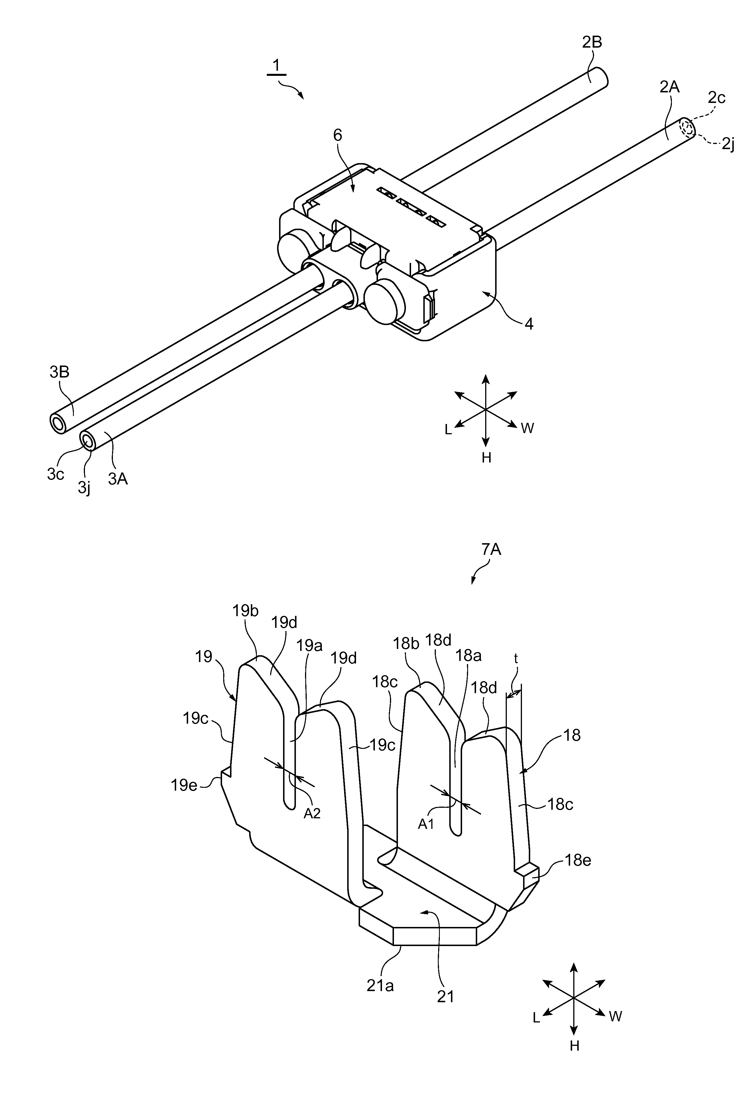
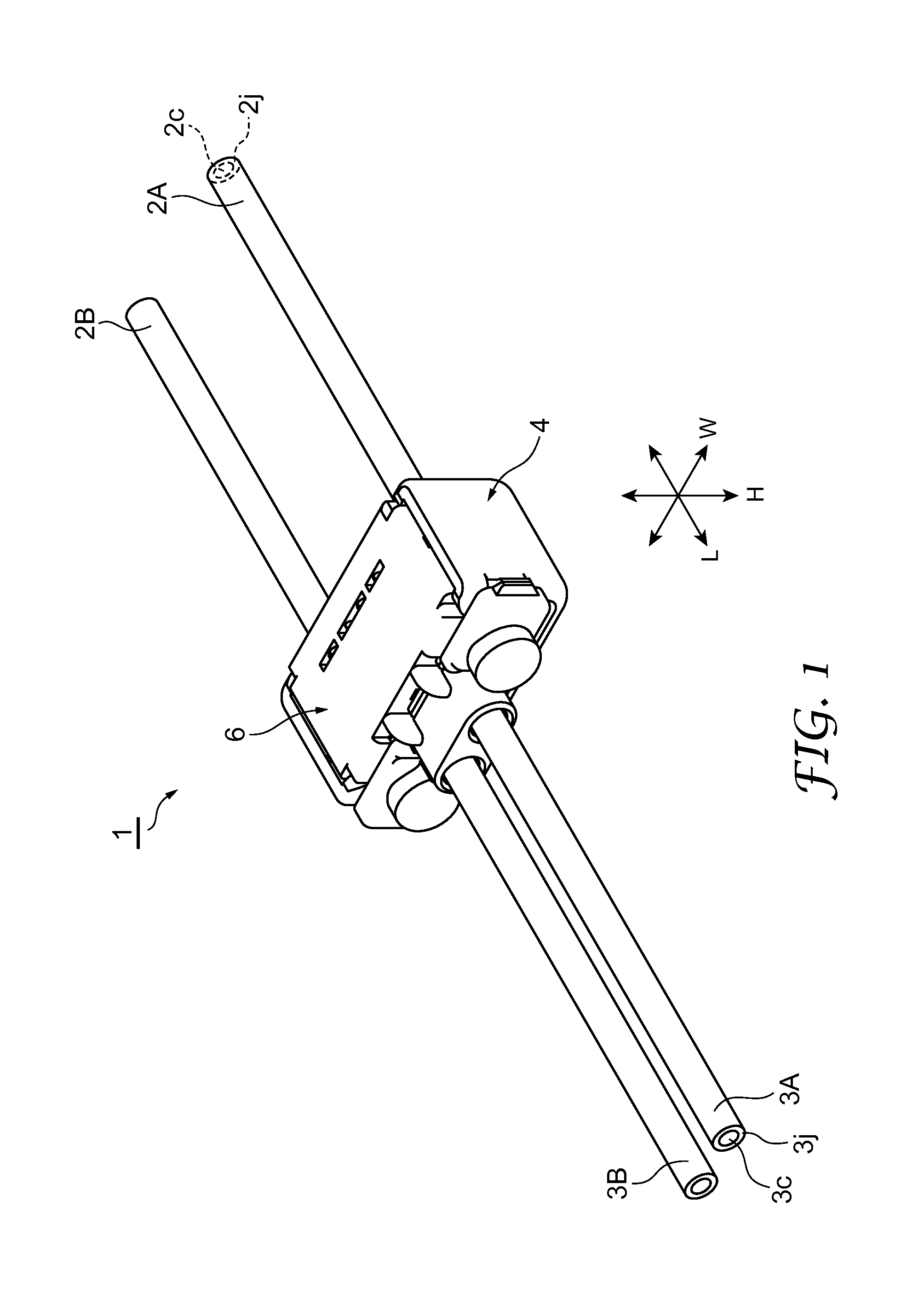
[0031]FIG. 1 is a perspective view illustrating a wire connector 1 according to this embodiment, illustrating a form of connecting main wires (first wires) 2A and 2B to extension wires (second wires) 3A and 3B. As illustrated in FIG. 1, the wire connector 1 electrically connects the main wire 2A to the extension wire 3A and the main wire 2B to the extension wire 3B. Note that in this embodiment, the term “wire” is used to m...


PUM


Abstract

A wire connector is described that suppresses the cutting of wires accidentally. The wire connector 1 includes a wire holder 6 that holds at least two wires, a contact 7A that electrically connects the two wires and a body 4 that holds the wire holder. The wire holder 6 includes first and second end faces 24 and 26, and a wire holding portion 25 that includes first and second holding portions 32, 33, 34 and 36. On the first end face 24, at portions of circumferential edge portions of the openings 34c and 36d of the second holding portions 34 and 36, protecting portions 23 that project from the first end face 24 and protect the wires are provided.

Description

FIELD OF INVENTION[0001]This invention relates to a wire connector.BACKGROUND ART[0002]Modes for connecting a plurality of wires include, for example, a mode of connecting a main wire to branch wires in order to allow branching of a signal or the like, and a mode of connecting a wire to another wire to increase wire length.[0003]An example of the former mode is a connector described in Japanese Unexamined Patent Application Publication No. 2002-151169. A branch connector includes: a connector body for holding a trunk-use twisted pair cable and a branch-use twisted pair cable; a pair of crimp terminals disposed in the connector body for electrically connecting the trunk-use twisted pair cable to the branch-use twisted pair cable; and a lid body fixed to the connector body. Provided at a first end of the crimp terminals are a crimping edge to which a portion partway along the trunk-use twisted pair cable is connected. Provided at a second end of the crimp terminals are a crimping edge...

Claims


Application Information

Patent Timeline
Patent Type & Authority Patents(United States)
IPC IPC(8): H01R4/24H01R13/518H01R11/09
CPCH01R4/245H01R4/2433H01R4/2429H01R4/2445H01R13/518H01R11/09H01R4/24H01R4/70H02G1/14
Inventor WASAI, KENTAOHSAWA, RENTAROOIKE, TOMOYASU
Owner CORNING RES & DEV CORP
Why Eureka
Try Eureka