
Vehicle far side airbag device

a technology for airbags and vehicles, which is applied in the direction of vehicular safety arrangements, pedestrian/occupant safety arrangements, vehicular components, etc., can solve the problems of uncontrollable gas ejection from the inflator inside swaying the upper portion of the airbag bag body, etc., to stabilize the deployment behavior of the airbag, the effect of quick split open

Active Publication Date: 2016-09-27
TOYOTA JIDOSHA KK
View PDF39 Cites 3 Cited by
  • Summary
  • Abstract
  • Description
  • Claims
  • Application Information

AI Technical Summary

Benefits of technology

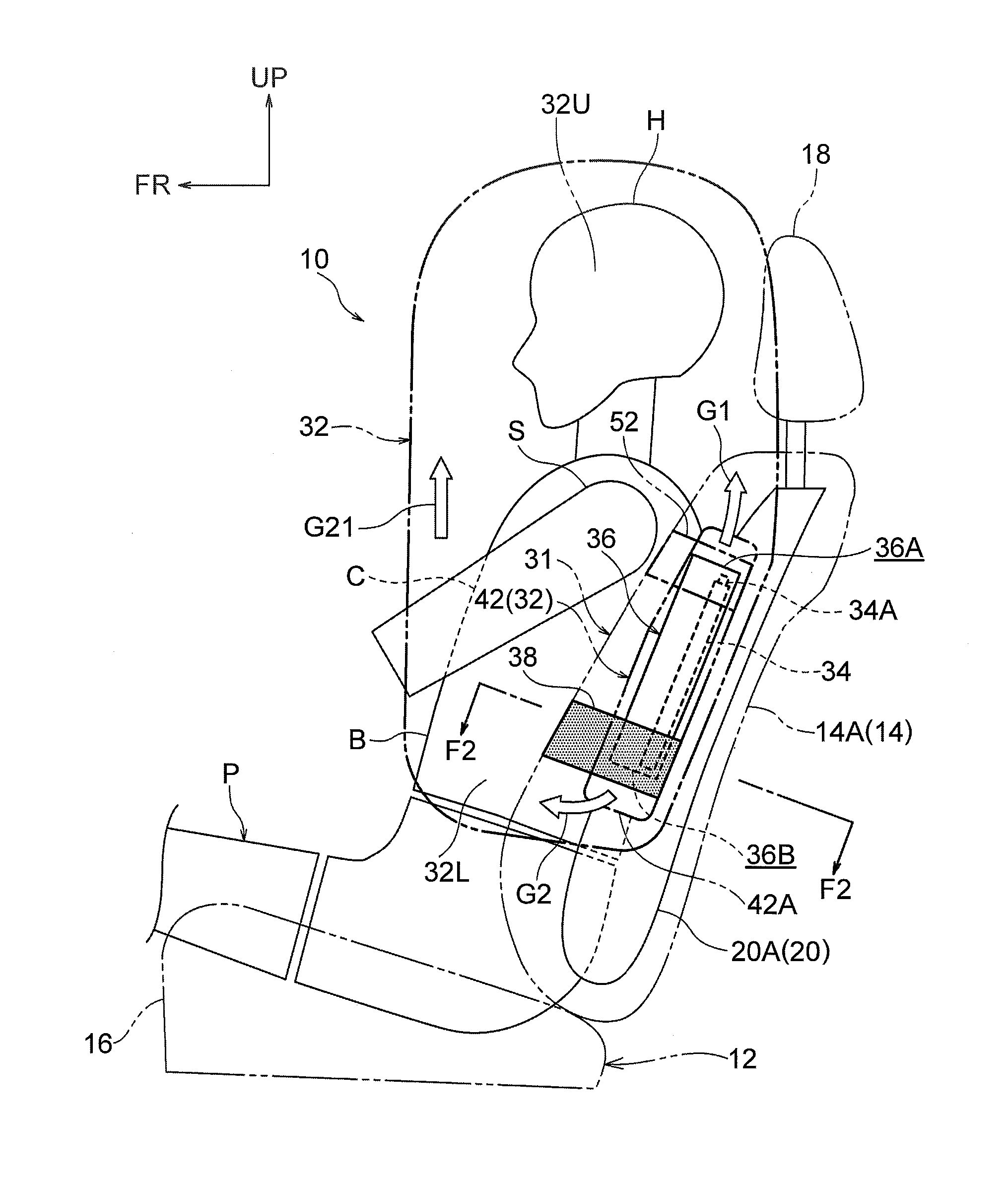
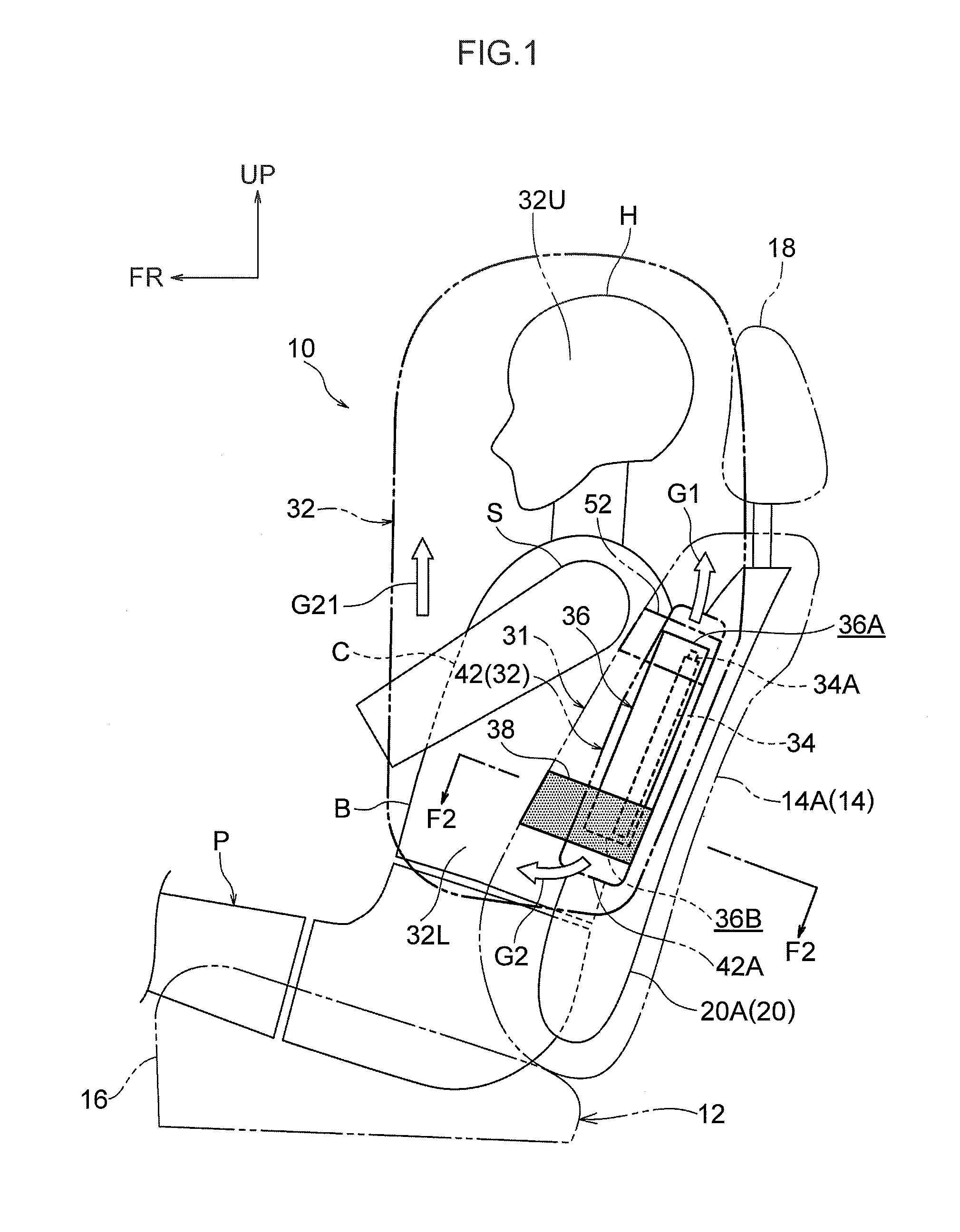
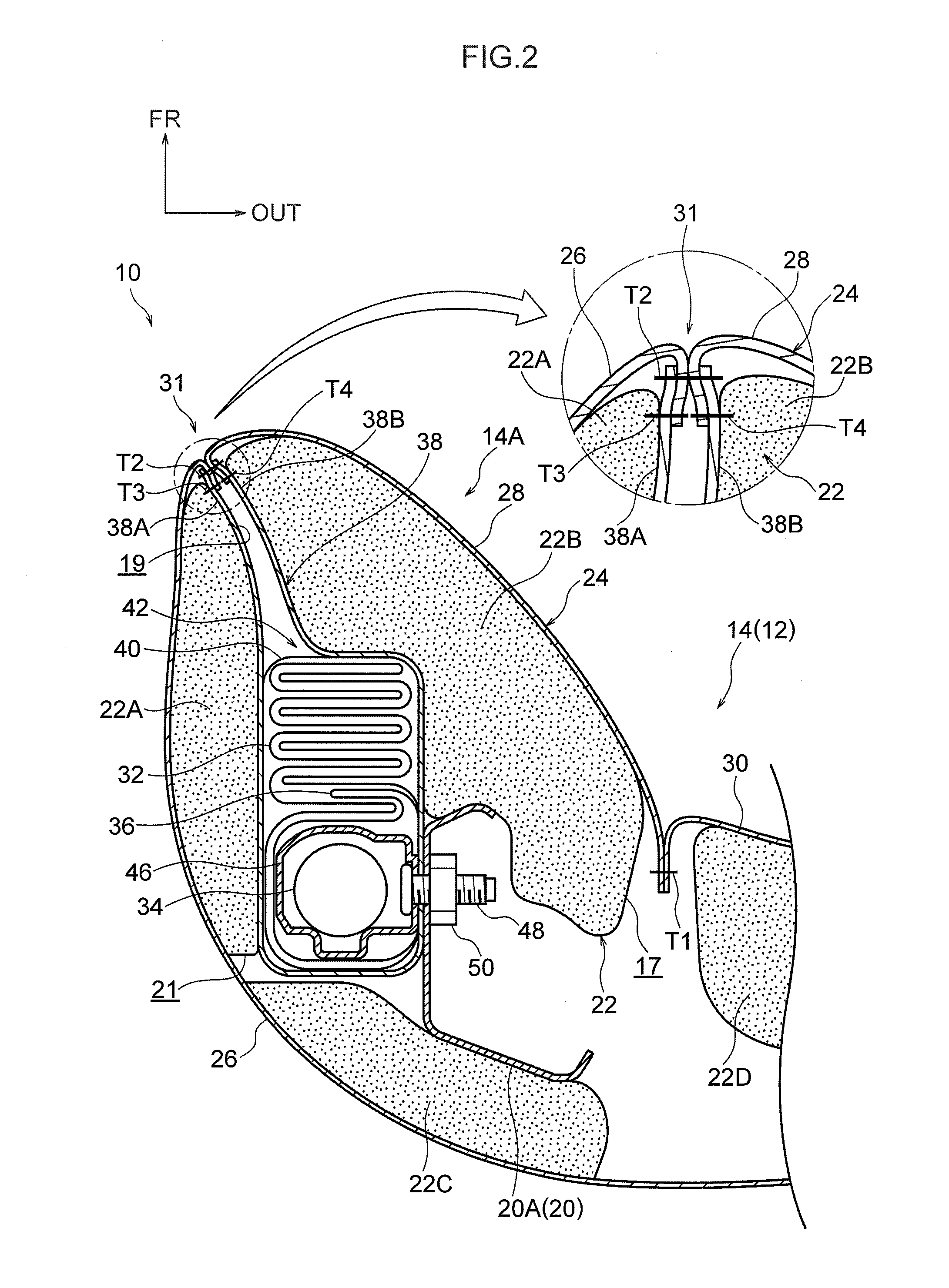
The present invention relates to a vehicle far side airbag device that helps stabilize the deployment behavior of the airbag. The device includes a diffuser with a predetermined splitting portion that splits open to allow the airbag to inflate and deploy. The device also includes a tensioning cloth which helps the airbag inflate at an early stage and a communication hole which allows some of the gas generated by the inflator to inflate and deploy the rear bag section at an earlier stage and at higher pressure than the front bag section, thereby contributing to stabilizing the deployment behavior of the airbag.

Problems solved by technology

However, the structure of the side airbag device described above is such that the airbag bag body is set with a large vehicle height direction dimension, and an upper portion of the airbag bag body, for protecting a head of an occupant, is not directly fixed to a seatback.
There is accordingly a possibility that the upper portion of the airbag bag body sways greatly during inflation and deployment in cases in which a flow of gas ejected from the inflator inside the airbag bag body is not well controlled.

Method used


Image

  • Vehicle far side airbag device
  • Vehicle far side airbag device
  • Vehicle far side airbag device

Examples


first modified example

[0057]FIG. 4 is a side view corresponding to FIG. 3, illustrating a first modified example 60 of a vehicle side airbag device according to an exemplary embodiment of the present invention. In the first modified example 60, the tensioning cloth 38 is disposed in a position superimposed on the lower end opening 36B of the diffuser 36 in the deployed state, and the lower end 42A of the package 42 in seat side view. Namely, in the first modified example 60, the tensioning cloth 38 is installed such that a portion thereof is positioned further to the lower side of the seatback 14 than the lower end opening 36B of the diffuser 36 in the deployed state, and the lower end 42A of the package 42.

[0058]In the first modified example 60, the airbag 32 in the stored state starts to inflate at an early stage at the height at which the above-mentioned portion of the tensioning cloth 38 is positioned due to high pressure gas being ejected from the lower end opening 36B, thereby enabling tension to a...

second modified example

[0059]FIG. 5 is a side view corresponding to FIG. 3, illustrating a second modified example 70 of a vehicle side airbag device according to an exemplary embodiment of the present invention. In the second modified example 70, the tensioning cloth 38 is disposed at a position superimposed on the lower end opening 36B of the diffuser 36 in the deployed state and the lower end 42A of the package 42 in seat side view, similarly to in the first modified example. However, in the second modified example 70, the lower end 42A of the package 42 is set further to the upper side of the seatback 14 than the lower end opening 36B of the diffuser 36 in the deployed state. Namely, in the second modified example 70, configuration is such that a lower end portion of the diffuser 36 is folded together with the lower end portion 32L of the airbag 32 when the airbag 32 is folded to form the package 42.

[0060]In the second modified example 70, the folded state of the lower end portion of the diffuser 36 i...

third modified example

[0061]FIG. 6 is a side view corresponding to FIG. 3, illustrating a third modified example 80 of a vehicle side airbag device according to an exemplary embodiment of the present invention. In the third modified example 80, the tensioning cloth 38 is disposed in a position superimposed on the lower end 42A of the package 42 in seat side view, and is disposed such that the entire tensioning cloth 38 is positioned further to the lower side of the seatback 14 than the lower end opening 36B of the diffuser 36 in the deployed state.

[0062]In the third modified example 80, the airbag 32 in the stored state starts to inflate at an early stage at the height at which the tensioning cloth 38 is disposed due to the high pressure gas being ejected from the lower end opening 36B, thereby enabling tension to act on the tensioning cloth 38 at an early stage due to the inflation pressure of the airbag 32. This enables basically the same operation and advantageous effects to be obtained as in the prev...


PUM


Abstract

A vehicle far side airbag device includes: a splitting portion at a front side of a seat cover, at a side section at a vehicle center side of vehicle seatback, extends along a height of the seatback; an airbag inside the side section, deploys toward an outside of the side section while splitting the splitting portion, to protect an occupant from head to abdomen; a diffuser housed at a lower and rear side within the airbag, ejects gas from an inflator from an upper end opening and a lower end opening; and a tensioning cloth fixed to both a seatback frame and a location at a lower end of the splitting portion, is superimposed on the airbag in a stored state. A portion of the tensioning cloth is positioned further to a seatback lower side than the lower end opening of the diffuser in a deployed state.

Description

CROSS-REFERENCE TO RELATED APPLICATION[0001]This application is based on and claims priority under 35 USC 119 from Japanese Patent Application No. 2014-209107 filed on Oct. 10, 2014, the disclosure of which is incorporated by reference herein.BACKGROUND[0002]1. Technical Field[0003]The present invention relates to a vehicle far side airbag device provided at a side section at a vehicle width direction center side of a seatback of a vehicle seat.[0004]2. Related Art[0005]In an airbag device (side airbag device) described in Japanese Patent Application Laid-Open (JP-A) No. 2012-051557, an airbag bag body includes an inflation location that inflates on receiving gas supplied from an inflator, and a non-inflation location. An opening is formed to the non-inflation location, and a tether inserted through the opening is connected to a rear end portion and a front end portion of the airbag bag body. A deployment trajectory of the airbag bag body is controlled by the tether.[0006]However, t...

Claims


Application Information

Patent Timeline
Patent Type & Authority Patents(United States)
IPC IPC(8): B60R21/261B60R21/207B60R21/2334B60R21/2165B60R21/268B60R21/231
CPCB60R21/261B60R21/207B60R21/2165B60R21/2334B60R21/23138B60R21/268B60R2021/23146B60R2021/161
Inventor FUJIWARA, YUSUKE
Owner TOYOTA JIDOSHA KK
Learn More