Vehicle side airbag device
a technology for side airbags and vehicles, which is applied in the direction of vehicular safety arrangments, pedestrian/occupant safety arrangements, vehicle components, etc., can solve the problems of swaying of the head protection section and inability to stably protect the head of the occupant, and achieve the effect of stabilizing the deployment behavior
- Summary
- Abstract
- Description
- Claims
- Application Information
AI Technical Summary
Benefits of technology
Problems solved by technology
Method used
Image
Examples
first modified example
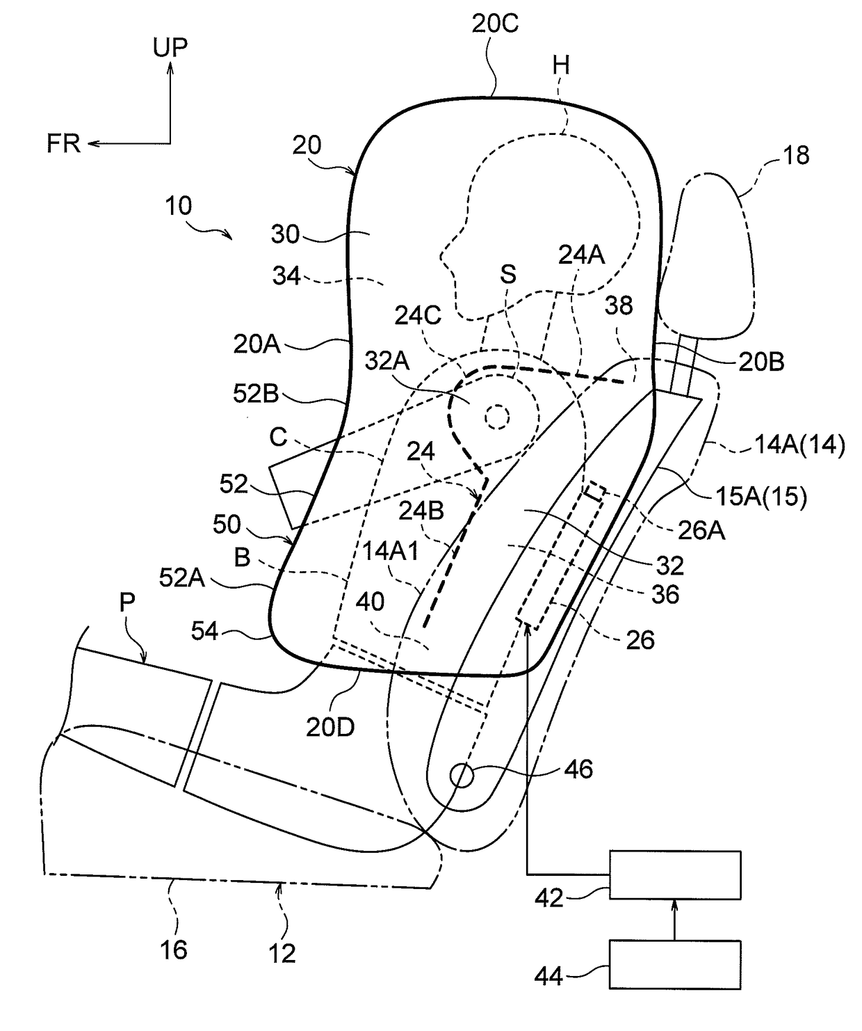
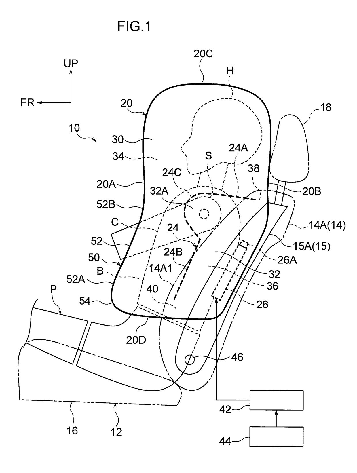
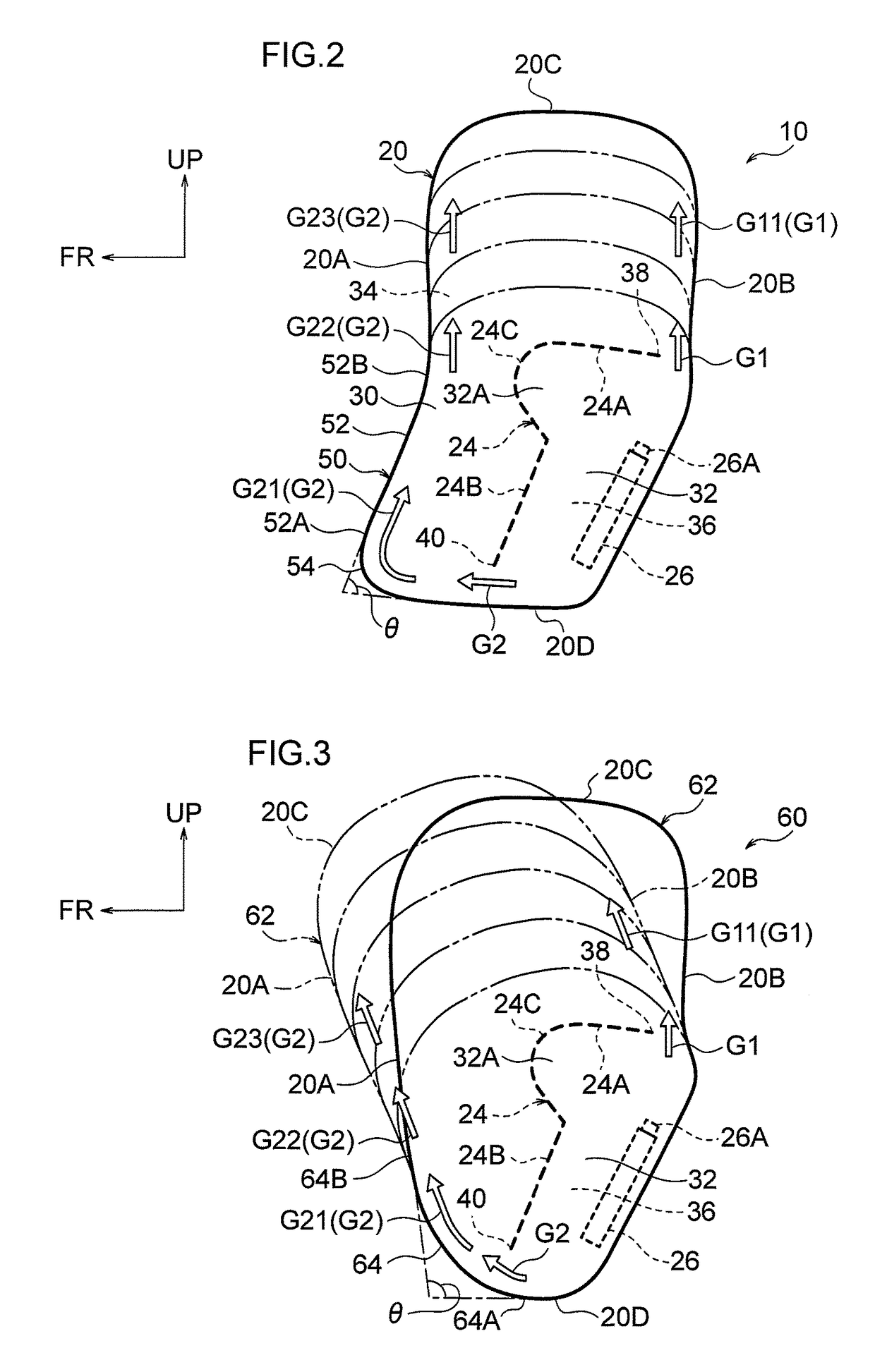
[0070]FIG. 4 is a side view corresponding to FIG. 2 and illustrating a first modified example 70 of a vehicle side airbag device according to an exemplary embodiment of the present invention. In the first modified example 70, the tether 24 does not include the circular arc shaped portion 24C, the upper end of the upright extension portion 24B is contiguous to the front end of the crosswise extension portion 24A, and the shoulder restraint portion 32A is omitted. In the first modified example 70, in the inflated and deployed state of the airbag 20, the projection amount of the rear bag section 32 from the front edge portion 14A1 of the center-side side section 14A (omitted from illustration in FIG. 4) can be reduced or set to zero. This enables the above-mentioned OOP performance to be improved. Note that the tether 24 (partitioning section) may be set as illustrated by the double-dotted dashed line in FIG. 4.
second modified example
[0071]FIG. 5 is a side view corresponding to FIG. 2, illustrating a second modified example 80 of a vehicle side airbag device according to an exemplary embodiment of the present invention. In the second modified example 80, the gas impeding section 50 includes a forward sloping portion 56 instead of the curved portion 54 according to the previous exemplary embodiment. The forward sloping portion 56 is formed extending diagonally toward the vehicle upper front from the front end of the lower edge portion 20D in the inflated and deployed state of the airbag 20, and an upper end of the forward sloping portion 56 is contiguous to the lower end 52A of the rearward sloping portion 52. The second modified example 80 also enables basically the same advantageous effects to be obtained to those of the previous exemplary embodiment.
third modified example
[0072]FIG. 6 is a side view corresponding to FIG. 2 and illustrating a third modified example 90 of a vehicle side airbag device according to an exemplary embodiment of the present invention. In the third modified example 90, a loop diffuser 92, serving as a flow regulating section, is provided instead of the tether 24 according to the previous exemplary embodiment. The loop diffuser 92 is also referred to as an inner tube, or a flow regulating cloth. The loop diffuser 92 is formed in the shape of a trumpet shaped tube using a similar cloth material to the base cloth of the airbag 20, for example, and is fixed to the side frame 15A by the inflator 26 housed inside. The loop diffuser 92 is formed with a truncated cone shaped external profile that increases in diameter on progression from an upper end opening 92A toward a lower end opening 92B. The upper end opening 92A corresponds to an “upper ejection opening” of the present invention, and the lower end opening 92B corresponds to a ...
PUM
 Abstract
Description
Claims
Application Information
 - R&D
- Intellectual Property
- Life Sciences
- Materials
- Tech Scout
- Unparalleled Data Quality
- Higher Quality Content
- 60% Fewer Hallucinations
Browse by: Latest US Patents, China's latest patents, Technical Efficacy Thesaurus, Application Domain, Technology Topic, Popular Technical Reports.
© 2025 PatSnap. All rights reserved.Legal|Privacy policy|Modern Slavery Act Transparency Statement|Sitemap|About US| Contact US: help@patsnap.com


