
Embolization coil

a technology of embolism coil and coil body, which is applied in the field of embolism coil, to achieve the effect of superior embolism coil and resistance to deterioration in delivery efficiency

Active Publication Date: 2016-10-25
KANEKA CORP
View PDF11 Cites 0 Cited by
  • Summary
  • Abstract
  • Description
  • Claims
  • Application Information

AI Technical Summary

Benefits of technology

[0025]The present invention provides a superior embolization coil resistant to breakage of the elongation-preventing wire thereof. The present invention also provides an embolization coil resistant to deterioration in delivery efficiency.

Problems solved by technology

However, even with such traditional technologies, there were still many problems to be studied, for example, for prevention of breakage of the elongation-preventing member (e.g., prevention of breakage when the coil is wound into a shape with a smaller diameter) and for improvement of the delivery efficiency of the embolization coil (efficiency in relocation of embolization coil in catheter and also in positional correction and relocation after withdrawal).

Method used


Image

  • Embolization coil
  • Embolization coil
  • Embolization coil

Examples


example 1

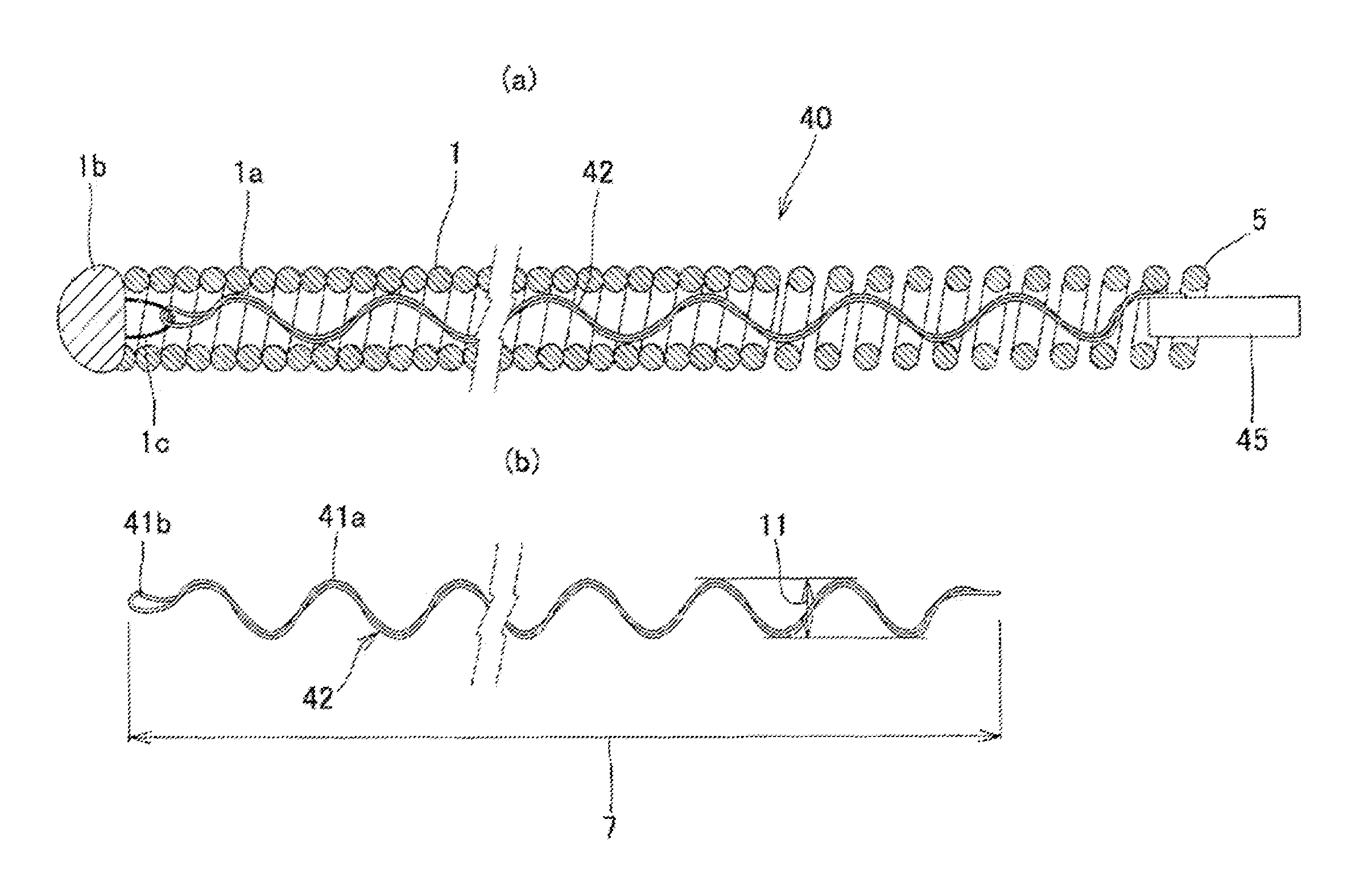
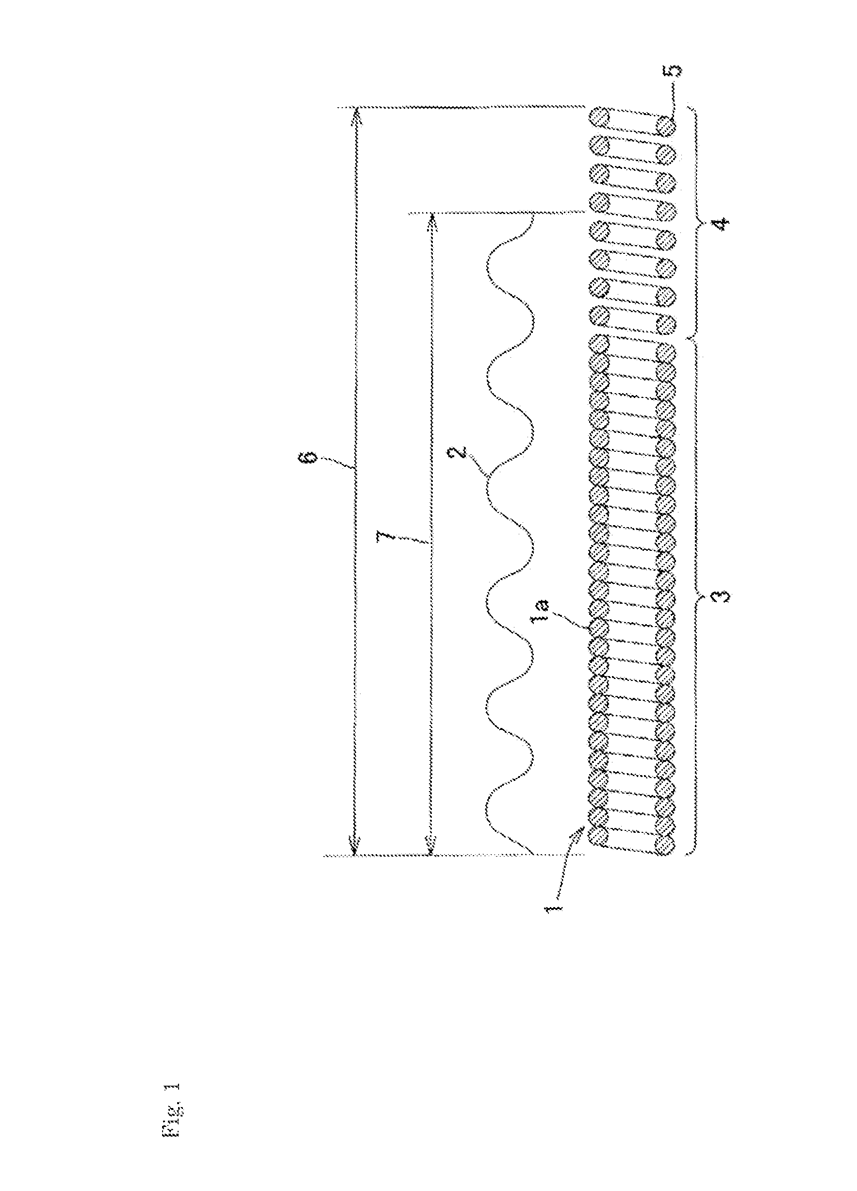
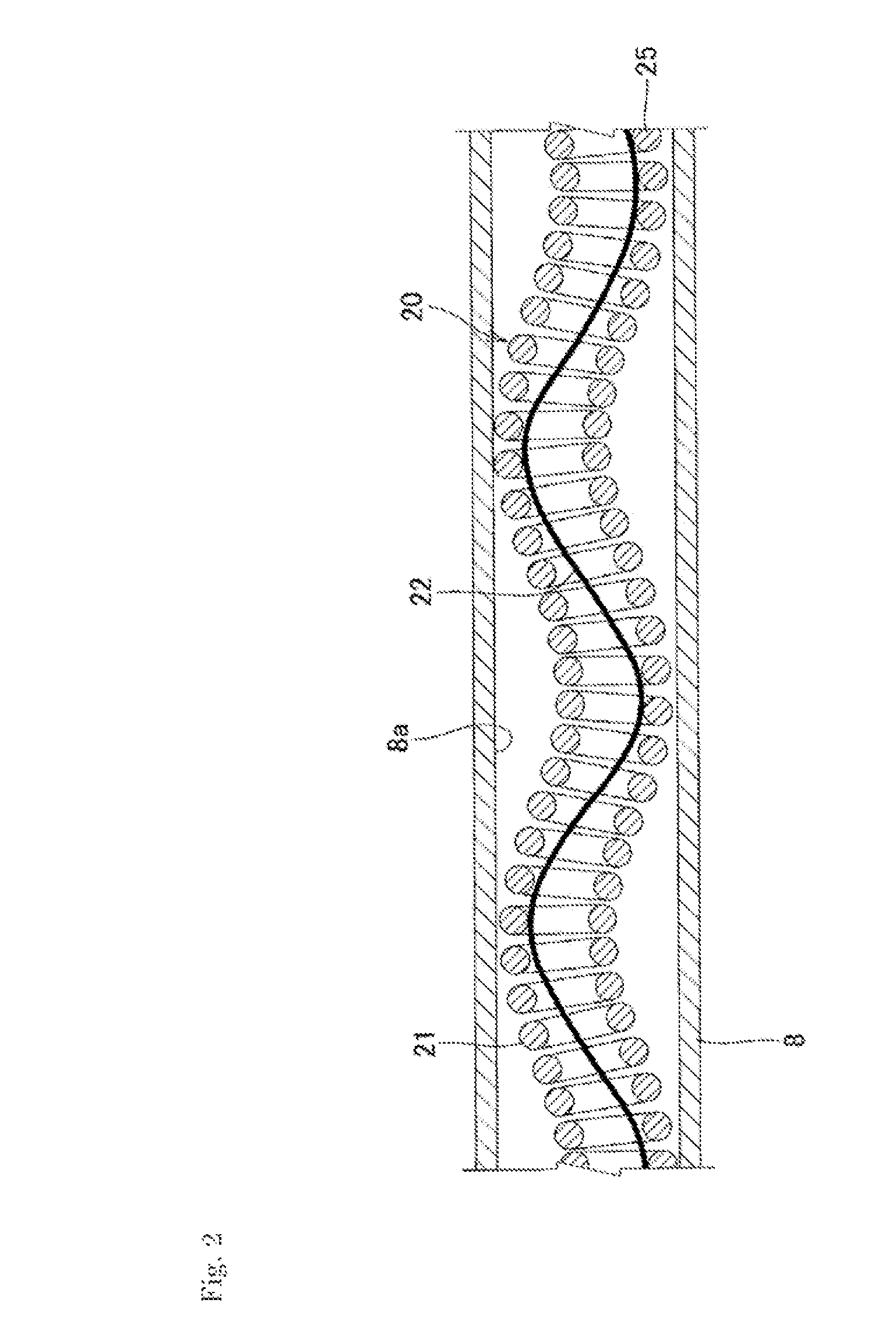
[0070]A metal coil made of a platinum-tungsten alloy wire (wire rod external diameter: 45 μm) having a coil internal diameter of 150 μm and a natural length of 200 mm was used. A pitch-wound region having a gap distance of 30% of the external diameter of the wire rod was formed in the proximal 30 mm region of the coil and a densely wound region in the other region. The rate of the pitch-wound region was 15%. A wire rod (twisted wire) of a platinum-tungsten alloy wire having a natural length of 195 mm in a wave shape at an amplitude of 100 μm was used as the expandable / shrinkable elongation-preventing wire. The maximum expandable length of the region placed between the following two points of the elongation-preventing wire was 115% with respect to the natural length of the region. The elongation-preventing wire was placed between the terminal two points of the coil, as it is elongated to a length of 200 mm, to give an embolization coil in a spiral secondary shape having a diameter of...


PUM


Abstract

An embolic coil configured in such a manner that the risk that a stretch preventing wire breaks is very small even if the embolic coil is wound to a diameter smaller than the diameter of a secondary shape of the coil imparted thereto and also in such a manner that the embolic coil has excellent deliverability. An embolic coil is configured in such a manner that a stretch preventing wire and a coil, a part or the whole of said coil being coarsely wound, are affixed to each other at at least two different points. The portion of the stretch preventing wire which is located between the two different portions is provided with a portion to which a stretchable shape has been imparted.

Description

CROSS REFERENCE TO RELATED APPLICATIONS[0001]The present application is the U.S. national stage entry under 35 U.S.C. 371 of PCT International Patent Application Serial No. PCT / JP2010 / 065513 filed on Sep. 9, 2010 which claims the benefit of priority to Japanese Patent Application Serial No. 2009-208737 filed Sep. 9, 2009, which are hereby incorporated by reference.TECHNICAL FIELD[0002]The present invention relates to an embolization coil for use in intravascular treatment. More specifically, it relates to an embolization coil for use in treatment of cerebral aneurysm or embolism of blood vessel.BACKGROUND ART[0003]Currently, intravascular treatments such as those using catheter have been known as less-invasive treatment methods for intravascular lesions such as aneurysm. The embolization coil used for placement at a targeted site such as blood vessel or aneurysm in these intravascular treatment methods needs to show various characteristics such as those shown below.[0004]First, the ...

Claims


Application Information

Patent Timeline
Patent Type & Authority Patents(United States)
IPC IPC(8): A61F2/01A61B17/12
CPCA61B17/12022A61B17/12109A61B17/12145A61B17/12154A61B17/00234A61B17/12113A61B17/12118
Inventor YAMANAKA, YASUSHIOGAWA, ATSUSHI
Owner KANEKA CORP
Learn More