Electronic control apparatus for electrically-driven vehicle
Active Publication Date: 2017-01-03
DENSO CORP
View PDF42 Cites 24 Cited by
Summary
Abstract
Description
Claims
Application Information
AI Technical Summary
This helps you quickly interpret patents by identifying the three key elements:
Problems solved by technology
Method used
Benefits of technology
[0007]It is therefore an object to improve maintenance of an electrically-driven v
Problems solved by technology
However, the regulation is not applicable to vehicles such as an electric vehicle and a fuel cell
Method used
Image
Click on the blue label to locate the original text in one second.
Reading with bidirectional positioning of images and text.
Examples
Example
First Embodiment
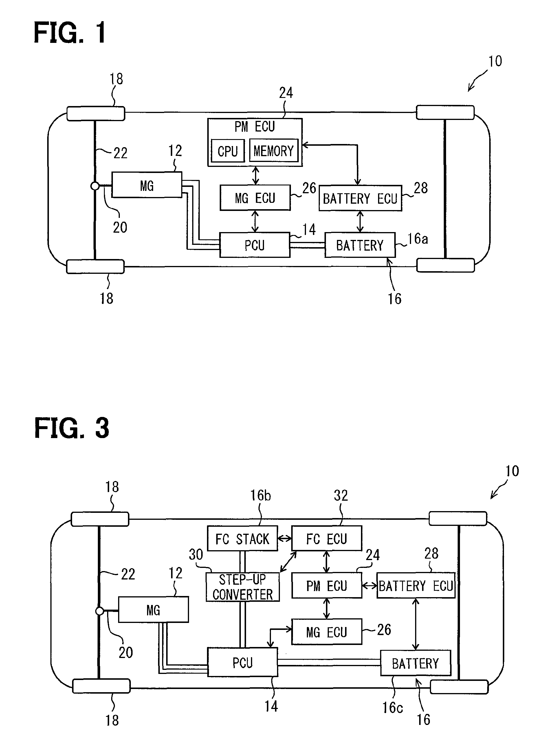
[0014]A vehicle incorporating a first embodiment will be described with reference to FIG. 1. A vehicle 10 shown in FIG. 1 is an electric vehicle, which has no internal combustion engine and is driven electrically by an electric motor. This electric vehicle may be a conventional one and hence no further details will be described.
[0015]The vehicle 10 includes a motor-generator 12 (referred to as MG 12 below) for generating travel torque, a power control unit (referred to as PCU 14 below) for controlling driving of the MG 12, and an electric power supply source 16 for supplying electric power to the MG 12.
[0016]The MG 12 among those components corresponds to a motor as a drive power source for vehicle travel. The electric power supply source 16 includes a battery 16a, which is a changeable and dischargeable secondary battery. The vehicle 10 is an FF (front-engine, front-wheel) drive type, in which left and right front wheels are drive wheels 18.
[0017]The MG 12 is, for e...
Example
Second Embodiment
[0047]An electronic control apparatus for an electrically-driven vehicle according to a second embodiment will be described next without repeating the description about the same components as the electronic control apparatus of the vehicle 10 in first embodiment.
[0048]As shown in FIG. 3, the vehicle 10 in the second embodiment is a fuel cell vehicle, which is electrically driven by an electric motor and does not have the internal combustion engine as the electric vehicle in the first embodiment did not have. Since the fuel cell vehicle may be conventional, no detail description about it will be made.
[0049]The vehicle 10 has the MG 12, the PCU 14, the electric power supply source 16, the PM ECU 24, the MG ECU 26 and the battery ECU 28 similarly to the electric vehicle shown in the first embodiment. However, the electric power source 16 has a fuel cell (FC) stack 16b and a battery 16c.
[0050]The FC stack 16b is formed of, for example, plural solid polymer electrolyte ...
PUM
Abstract
An electronic control apparatus controls am electrically-driven vehicle, which has no engine but has only a motor supplied with electric power from an electric power supply source. The electronic control apparatus has a self-diagnosis function for storing an abnormality code corresponding to a diagnosis object when abnormality of the diagnosis object is detected. The electronic control apparatus checks whether the motor and the electric power supply source are operating normally when a power control switch is turned on under a state that the abnormality code is stored in a memory. The electronic control apparatus checks whether abnormality is detected again in the diagnosis object, the abnormality code of which has already been stored, when the motor and the electric power supply source are operating normally. The electronic control unit erases the abnormality code when no abnormality is detected again.
Description
CROSS REFERENCE TO RELATED APPLICATION[0001]This application is based on Japanese patent application No. 2014-16776 filed on Jan. 31, 2014, the disclosure of which is incorporated herein by reference.TECHNICAL FIELD[0002]The present disclosure relates to an electronic control apparatus, which controls an electrically-driven vehicle having, as a drive power source for travel, no engine but an electric motor supplied with electric power from an electric power source, and has a self-diagnosis function.BACKGROUND ART[0003]As disclosed in JP-A-H07-83867 (U.S. Pat. No. 5,454,259), a conventional electronic control apparatus controls a vehicle having an engine as a drive power source for vehicle travel and has a self-diagnosis function.[0004]This electronic control apparatus is configured to store an abnormality code corresponding to a diagnosis object or item at the time of detection of abnormality of the diagnosis object. The electronic control apparatus is configured to erase the abnorm...
Claims
Application Information
Patent Timeline
Application Date:The date an application was filed.
Publication Date:The date a patent or application was officially published.
First Publication Date:The earliest publication date of a patent with the same application number.
Issue Date:Publication date of the patent grant document.
PCT Entry Date:The Entry date of PCT National Phase.
Estimated Expiry Date:The statutory expiry date of a patent right according to the Patent Law, and it is the longest term of protection that the patent right can achieve without the termination of the patent right due to other reasons(Term extension factor has been taken into account ).
Invalid Date:Actual expiry date is based on effective date or publication date of legal transaction data of invalid patent.