
Network monitoring system, server apparatus, network monitoring method

Inactive Publication Date: 2010-09-02
NEC CORP +1
View PDF5 Cites 3 Cited by
  • Summary
  • Abstract
  • Description
  • Claims
  • Application Information

AI Technical Summary

Benefits of technology

[0015]It is an exemplary object of this invention to provide a network monitoring system, a server apparatus, and a network monitoring method used thereto, which are capable of improving extra maintenance.

Problems solved by technology

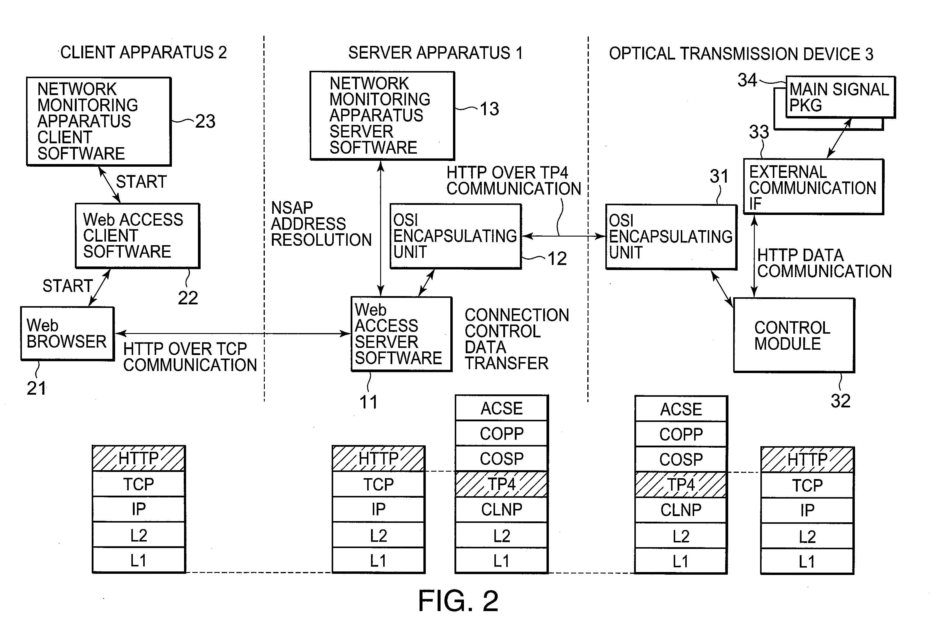
Inasmuch as different protocols are used in the above-mentioned transmission network such that the first protocol (the TCP / IP protocol) is used between the second network monitoring apparatus (the client apparatus) and the first network monitoring apparatus (the server apparatus) and the second protocol (the OSI protocol) is used between the first network monitoring apparatus (the server apparatus) and the optical transmission device, there is a problem such that it is impossible to render a service using a Web browser for the optical transmission device via the OSI protocol (the second protocol).
It is therefore impossible to use a Web server function mounted on the optical transmission device.
Accordingly, it is necessary to develop renewed special-purpose software for performing access for the optical transmission device and it results in increasing development costs.
In addition, it is necessary for a user to entail purchase expenses of the special-purpose software and this becomes a factor that cannot cut initial costs.
In addition, if the special-purpose software is not mounted on a maintenance terminal to be operated on performing maintenance by the user, it is impossible to access the optical transmission device.
Furthermore, if the special-purpose software matched with version of the optical transmission device cannot be not prepared, a mismatch occurs between the optical transmission device and version of the special-purpose software and it results in occurring a problem such that it is impossible to access the optical transmission device.
As a result, in technique disclosed in the Patent Document 1, it is impossible to resolve the problem in a case of using the different protocols.

Method used


Image

  • Network monitoring system, server apparatus, network monitoring method
  • Network monitoring system, server apparatus, network monitoring method
  • Network monitoring system, server apparatus, network monitoring method

Examples


Embodiment Construction

[0023]Now, the description will be made as regards an embodiment of a network monitoring system, a server apparatus, a network monitoring method, and a program according to this invention with reference of attached drawings.

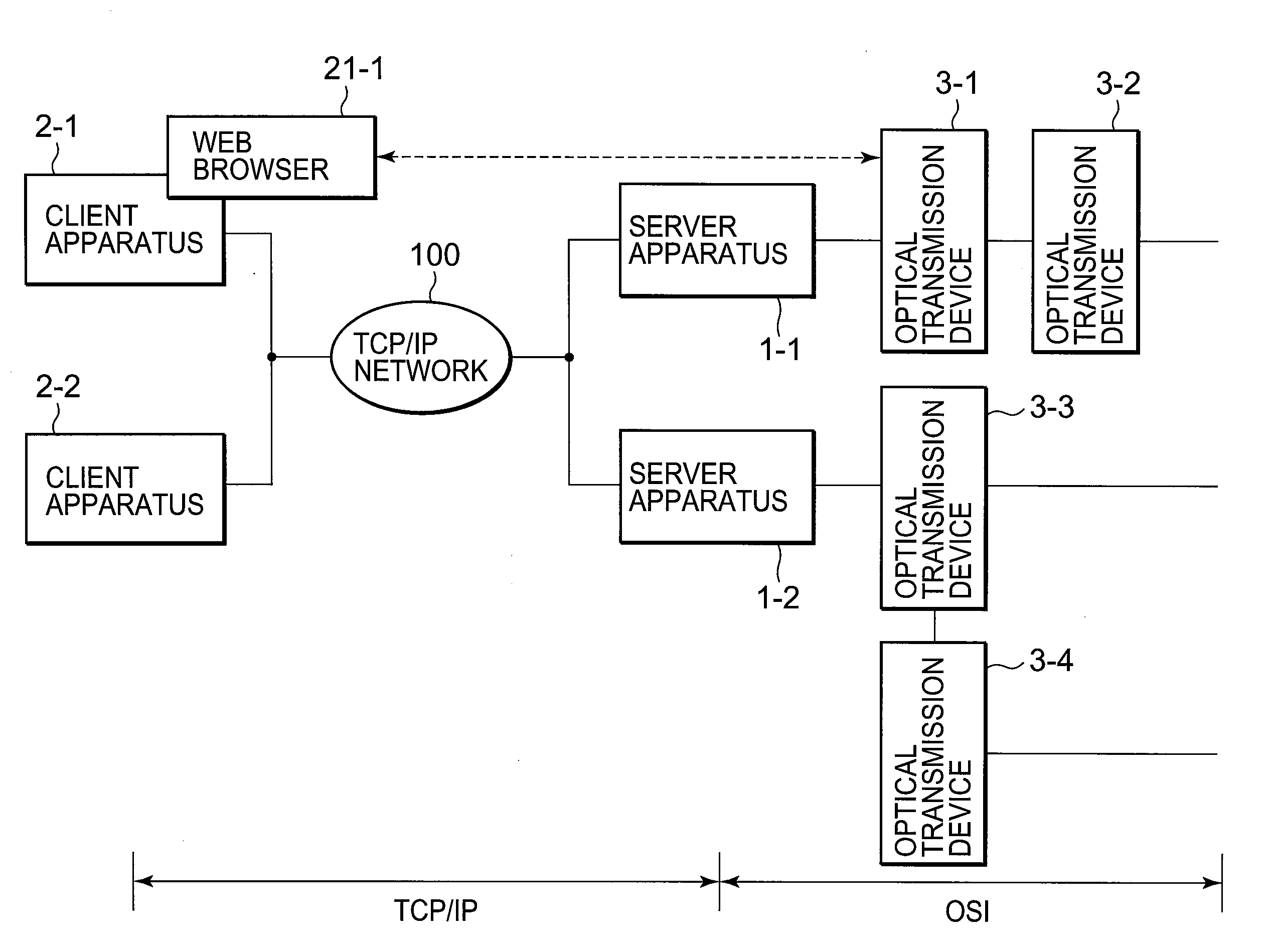
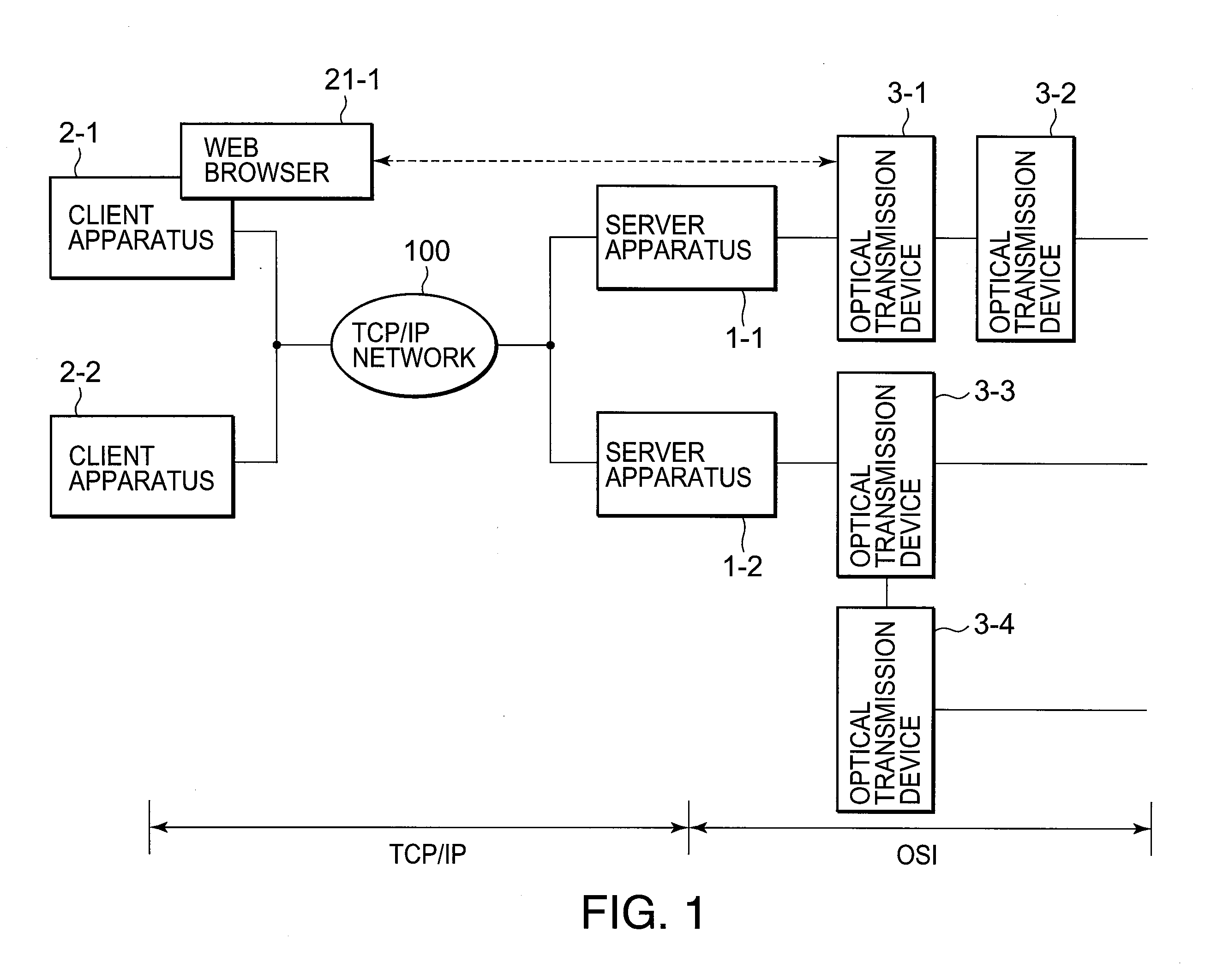
[0024]FIG. 1 is a block diagram showing construction of the network monitoring system according to an exemplary embodiment of this invention. The illustrated network monitoring system comprises first and second server apparatuses 1-1 and 1-2, first and second client apparatuses 2-1 and 2-2, and first through fourth optical transmission devices 3-1, 3-2, 3-3, and 3-4. Each of the first and the second server apparatuses 1-1 and 1-2 is also called a first network monitoring apparatus while each of the first and the second client apparatuses 2-1 and 2-2 is also called a second network monitoring apparatus. Each of the first through the fourth optical transmission devices 3-1 to 3-4 comprises, for example, a ROADM (Reconfigurable Optical Add Drop Multiplexer) device. ...


PUM


Abstract

A network monitoring system includes a server apparatus managing information of an optical transmission device in a network configured in a ring fashion and a client apparatus carrying out at least change of setting of the optical transmission device and check of apparatus condition thereof. A first protocol is used between the server apparatus and the client apparatus while a second protocol is uses between the server apparatus and the optical transmission apparatus. The first protocol and the second protocol are different from each other. The server apparatus includes a conversion portion carrying out mutual conversion between the first protocol and the second protocol.

Description

TECHNICAL FIELD [0001]This invention relates to a network monitoring system, a server apparatus, and a network monitoring method used therein and, in particularly, to a network monitoring method in a communication system where a communication protocol between the server apparatus and a client apparatus in the network monitoring system and a communication protocol between the server apparatus and an optical transmission device in the network monitoring system are different from each other.BACKGROUND ART [0002]As a transmission network related to this invention, there is a high-speed and a large-capacity network by comprising a plurality of ROADM (Reconfigurable Optical Add Drop Multiplexer) devices configured in a ling fashion by an optical fiber in a ring fashion and by combining a wavelength multiplexing method and technique of pass management. Each ROADM device is a kind of an optical transmission device.[0003]As a system for monitoring such as the above-mentioned network, first n...

Claims


Application Information

Patent Timeline
IPC IPC(8): G06F15/173G06F15/16
CPCH04L12/2602H04L12/42H04L43/00H04L41/0253H04L41/0226
Inventor HASHIMOTO, YUSAKU
Owner NEC CORP
Learn More