Connector

Active Publication Date: 2017-03-07
JAPAN AVIATION ELECTRONICS IND LTD
View PDF4 Cites 3 Cited by
  • Summary
  • Abstract
  • Description
  • Claims
  • Application Information

AI Technical Summary

Benefits of technology

[0015]wherein, as the operation member is brought to a closed position while the connection end portion of the connection target is inserted in the insertion portion, the lock portion is fitted in a lock receiving portion of the connection target to p

Problems solved by technology

If the operation member 4 comes off the housing 2, the contacts 5 hooked on the operation member 4 ma

Method used


Image

  • Connector
  • Connector
  • Connector

Examples


Embodiment Construction

[0029]An embodiment of the present invention will be described below based on the appended drawings.

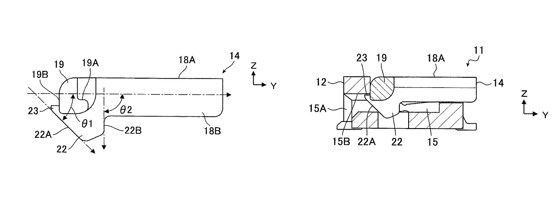
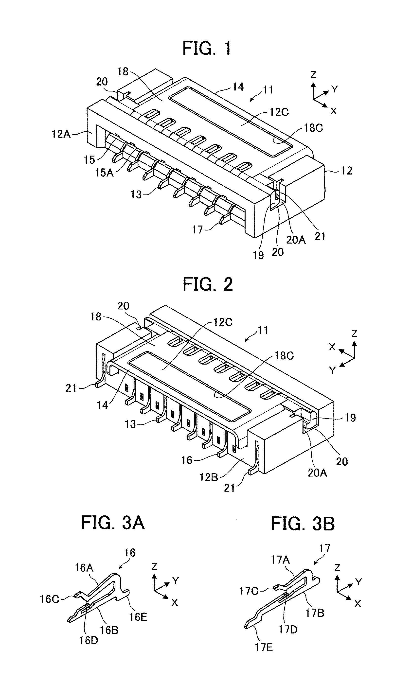
[0030]FIGS. 1 and 2 show the structure of a connector 11 according to the embodiment. The connector 11 is a small connector for connection with connection targets such as a flexible printed circuit (FPC), a flexible flat cable (FFC), a rigid circuit board, and other printed wiring boards, the connection targets each having a sheet-like base on a surface of which a conductive pattern is disposed. The connector 11 includes a housing 12 having a substantially cuboid outer shape elongated in the width direction, a plurality of contacts 13 arranged in the width direction of the housing 12 and extending from the front surface 12A side of the housing 12 toward the rear surface 12B side, and an operation member 14 attached to the housing 12.

[0031]The housing 12 is provided with a recess-like insertion portion 15, and an insertion opening 15A of the insertion portion 15 opens toward the front ...


PUM


Abstract

A connector has a housing including an insertion portion, a recess-shaped shaft receiving portion opening in an opening direction and an abutment surface facing in an opposite direction from the opening direction, and an operation member held by the housing rotatably around an axis direction of a rotation shaft portion inserted in the shaft receiving portion, the operation member including a lock portion and a projection, as the operation member is brought to a closed position while a connection end portion of a connection target is inserted in the insertion portion, the lock portion is fitted in a lock receiving portion of the connection target to prohibit pull-out of the connection end portion of the connection target from the insertion portion, and the projection comes into contact with the abutment surface to prohibit movement of the operation member in the opening direction.

Description

BACKGROUND OF THE INVENTION[0001]The present invention relates to a connector, in particular, to a connector that may be connected to connection targets such as a flexible printed circuit (FPC), a flexible flat cable (FFC), a rigid circuit board and other printed wiring boards, the connection targets each comprising a sheet-like base on a surface of which a conductor pattern is disposed.[0002]The FPC here refers to one in which conductive foil (mostly copper foil) is stuck to a flexible film-like insulator base (mostly polyimide), and the conductive foil is subjected to etching by means of lithographic technique to form wiring. The FFC refers to a cable in which flat-shaped conductors are disposed in an alignment and are covered by a sheet-like insulator. The rigid circuit board refers to one in which conductive foil (mostly copper foil) is stuck to a rigid insulator base (mostly glass epoxy), and the conductive foil is subjected to etching by means of lithographic technique to form...

Claims


Application Information

Patent Timeline
IPC IPC(8): H01R13/62H01R12/72H01R13/629H01R12/77H01R12/88
CPCH01R12/721H01R13/62977H01R12/88H01R12/774
Inventor ASHIBU, KENTA
Owner JAPAN AVIATION ELECTRONICS IND LTD
Why Eureka
Try Eureka