Tool exchanger, tool magazine, and machine tool

a tool exchanger and tool magazine technology, applied in the field of tool exchangers, tool magazines, and machine tools, can solve the problems of poor efficiency of work, difficult to realize, dangerous effects

Active Publication Date: 2013-07-04
MAKINO MILLING MASCH CO LTD
View PDF4 Cites 0 Cited by
  • Summary
  • Abstract
  • Description
  • Claims
  • Application Information

AI Technical Summary

Benefits of technology

[0012]Further, the present invention provides a machine tool provided with the above tool exchanger and a tool magazine having a drive portion for moving a tool stored in the tool storage part, including a detecting portion detecting whether the holder is at a retracted position where the holder is retracted from the tool storage part; and a control portion controlling the drive portion so as to permit a movement of the tool storage part if the detecting portion detects that the holder is at the retracted position and so as to prohibit the movement of the tool storage part if the detecting portion detects that the holder is not at the retracted position.

Problems solved by technology

However, in the tool exchanger described in Patent Literature 1, the work of pulling out and inserting tools is carried out near the pots, so there are other tools present in the work area and therefore the work is poor in efficiency and is dangerous.
Further, the simple structure tool exchanger for exchanging tools of a ring-shaped tool magazine described in Patent Literature 2 or 3 is difficult to realize.Japanese Unexamined Patent Publication No. 2009-56547 A1Japanese Examined Patent Publication No. 3877560 B2U.S. Pat. No. 6,857,995 B2

Method used


Image

  • Tool exchanger, tool magazine, and machine tool
  • Tool exchanger, tool magazine, and machine tool
  • Tool exchanger, tool magazine, and machine tool

Examples


Embodiment Construction

[0020]Below, referring to FIG. 1 to FIG. 7, an embodiment of a tool exchanger according to the present invention will be explained.

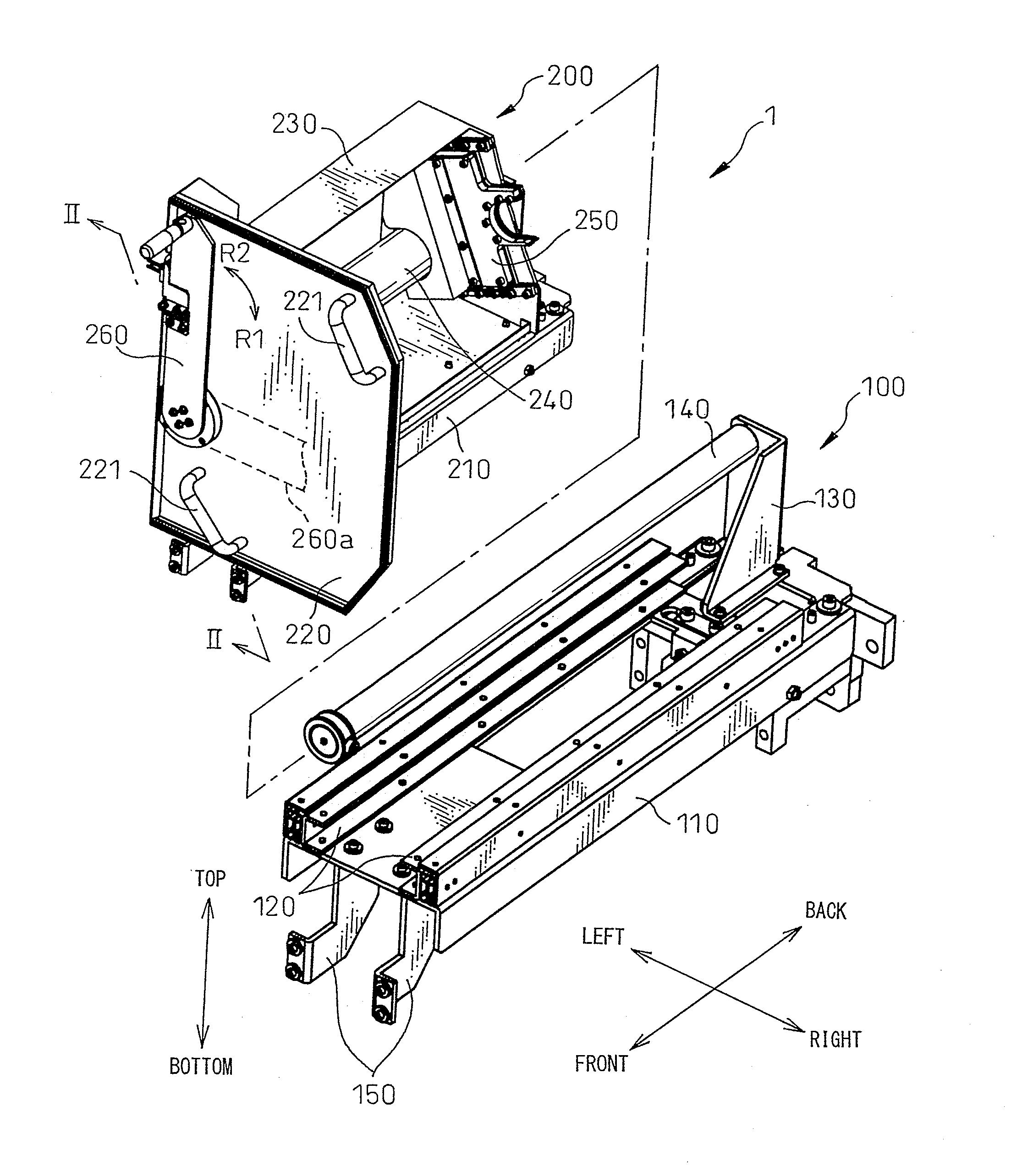
[0021]FIG. 1 is a disassembled perspective view which shows the configuration of a tool exchanger 1 according to an embodiment of the present invention. This tool exchanger 1, as shown in FIG. 3, is used for storing a tool 10 in a tool pot 302 of a tool magazine 300 and taking out a tool 10 from a tool pot 302. As shown in FIG. 1, the tool exchanger 1 according to the present embodiment has a base frame 100 and a slider 200 which is slidably mounted on the base frame 100. Note that, for convenience, the front, back, left, and right directions and the top and bottom directions are defined as illustrated. Below, these definitions will be followed to explain the configuration of the parts.

[0022]The base frame 100 has a base plate 110 which extends in the front-back direction, a left and right pair of rails 120 which extend on the base plate 110 in the front...


PUM


Abstract

A tool exchanger for storing a tool (10) with a holding groove (12) formed at a periphery of the tool in a plurality of tool storage parts (302) provided in a tool magazine (300) so that a tool axis becomes substantially horizontal in direction, and taking out the tool from the tool storage parts (302), the tool exchanger including: a base part (100); a slider (200) provided in a side of the tool storage parts (302) slidably relative to the base part (100) in a direction substantially parallel to the tool axis; a holder (250) attached to the slider (200) in a movable manner relative to the slider, and having an engagement part (252) which engages with the holding groove (12) of the tool; and a moving portion moving the holder (250) relative to the slider (200), wherein the moving portion includes: a handle part (260) for exerting a rotary force about an axis extending substantially parallel to the tool axis; a first cam mechanism (250, 242) moving the holder in a plane substantially perpendicular to the tool axis in accordance with a first turning operation of the handle part (260); and a second cam mechanism (161, 270) moving the holder (250) along a direction of the tool axis in accordance with a second turning operation of the handle part (260) successive to the first turning operation.

Description

REFERENCE TO RELATED APPLICATIONS[0001]This application is the national stage application under 35 USC 371 of International Application No. PCT / JP2010 / 066112, filed Sep. 10, 2010, the entire contents of which are incorporated herein by reference.FIELD OF THE INVENTION[0002]The present invention relates to a tool exchanger which stores a tool in a tool magazine and takes out a tool from the tool magazine and to a tool magazine and a machine tool which have such a tool exchanger.BACKGROUND OF THE INVENTION[0003]As a device for storing a tool in a tool magazine and taking out a tool from the tool magazine, in the past the device such as described in the following Patent Literature 1 has been known, which describes a tool attacher designed so that an attachment lever is operated to insert a tool in a pot of a tool magazine and to pull out a tool from the pot.[0004]However, in the tool exchanger described in Patent Literature 1, the work of pulling out and inserting tools is carried out ...

Claims


Application Information

Patent Timeline
Patent Type & Authority Applications(United States)
IPC IPC(8): B23Q3/157B23Q3/155
CPCB23Q3/157B23Q3/15526B23Q3/1554Y10T483/1864B23Q3/1572Y10T483/18Y10T483/13B23Q3/15713B23Q3/15722B23Q2003/15527B23Q2003/15532B23Q2003/155407Y10T483/176Y10T483/1779Y10T483/1827Y10T483/1836B23Q3/15533B23Q11/08B23Q17/007
Inventor NAKAHATA, AKIRAMISAKI, ETSUROKANAMARU, TETSUYAKOMATSUBARA, HIDEO
Owner MAKINO MILLING MASCH CO LTD
Why Eureka
Try Eureka