Internal combustion engine with variable valve control system

a control system and combustion engine technology, applied in valve arrangements, machines/engines, mechanical equipment, etc., can solve the problems of difficult to make the end face strong enough to withstand impact, not allowing the position, etc., to prevent the sliding movement of the rocker, reduce the influence of the engagement nail, and form easily without increasing the number of components

Inactive Publication Date: 2013-04-09
HONDA MOTOR CO LTD
View PDF26 Cites 0 Cited by
  • Summary
  • Abstract
  • Description
  • Claims
  • Application Information

AI Technical Summary

Benefits of technology

[0015]According to the first aspect of the present invention, the stopper that engages with the rocker arm to prohibit the sliding movement of the rocker. In addition, when the stopper disengages from the rocker arm to allow the sliding movement of the rocker arm, the position-restriction means formed in the rocker arm abuts on the stopper so that the sliding movement of the rocker arm can be restricted within a predetermined amount. Consequently, the sliding movement of the rocker arm can be restricted within the predetermined amount by means of a simple structure without increasing the number of component parts.
[0016]According to the second aspect of the present invention, the position-restriction means is formed as a protrusion that has a sidewall contiguously formed from the sidewall of the engagement groove. Accordingly, when the engagement nail disengages from the engagement groove, the engagement nail can be guided smoothly along the sidewall of the engagement groove. Consequently, the restriction imposed by the engagement nail on the sliding movement of the rocker arm can be cancelled smoothly. In addition, the position-restriction means can be formed easily.
[0017]According to the third aspect of the present invention, the protruding piece that is formed as a separate body from the engagement nail abuts on the position-restriction means of the rocker arm. Accordingly, in contrast to the case where the restriction on the sliding movement of the rocker arm is imposed by the engagement nail alone, the load that derives from the restriction on the sliding movement of the rocker arm can be received also by the protruding piece. The influence on the engagement nail can be reduced so that the restriction imposed on the sliding movement of the rocker arm can be accomplished reliably and accurately.
[0018]According to the fourth aspect of the present invention, both the engagement nail and the protruding piece are formed as parts of the plate-shaped member that extends from the support-shaft side of the stopper towards the rocker arm. Consequently, the engagement nail and the protruding piece can be formed easily without increasing the number of component parts.
[0019]In addition, the engagement nail and the protruding piece are formed so as to be separated from each other with the cut-away portion in between. Consequently, the influence that the abutting of the protruding piece on the position-restriction means has on the engagement nail can be reduced.
[0020]According to the fifth aspect of the present invention, the engagement nails are connected with each other and the protruding pieces are connected with each other so that the engagement nails and the protruding pieces can have higher rigidity. In addition, the portion in the vicinity of the vertex of the cut-away portion that has a chevron shape when viewed in the axial direction of the support shaft (i.e., in the vicinity of the support shaft) can be reinforced. Consequently, the influence that the abutting of the protruding piece on the position-restriction means has on the engagement nail can further be reduced.

Problems solved by technology

The layout of the bearing, however, sometimes does not allow the position-restriction means to be disposed at an appropriate position for the restriction on the sliding movement.
In addition, the end face of the bearing is usually made of an aluminum alloy, so that it is difficult to make the end face strong enough to withstand the impact given by the sliding movement of the rocker arm.

Method used


Image

  • Internal combustion engine with variable valve control system
  • Internal combustion engine with variable valve control system
  • Internal combustion engine with variable valve control system

Examples


Embodiment Construction

[0056]An embodiment of the present invention will now be described, with reference to the drawings. Throughout this description, relative terms like “upper”, “lower”, “above”, “below”, “front”, “back”, and the like are used in reference to a vantage point of an operator of the vehicle, seated on the driver's seat and facing forward. It should be understood that these terms are used for purposes of illustration, and are not intended to limit the invention.

[0057]An embodiment of the present invention is now described by referring to the drawings. In the following description, the terms indicating directions, such as forwards, rearwards, leftwards, and rightwards, refer to their respective ones seen from the driver of the vehicle. The arrows FR, LH, and UP in the drawings indicate the front-side, the left-hand side, and the upside of the vehicle, respectively.

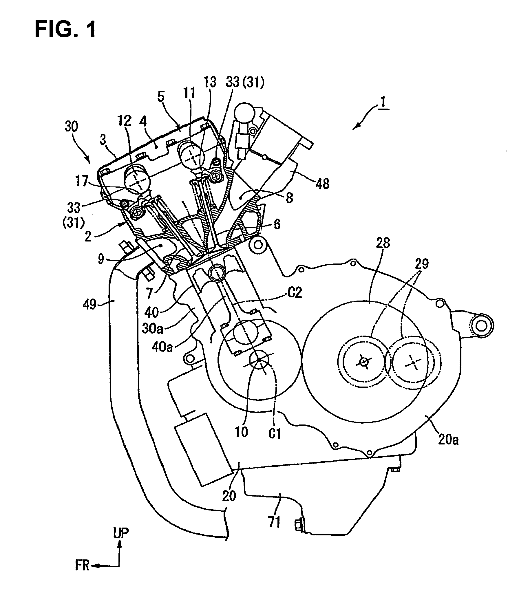
[0058]FIG. 1 shows a left-side view of an engine (internal combustion engine) 1, which is the prime mover of a saddle-ride type ...


PUM


Abstract

An internal combustion engine is equipped with a variable valve control system which is operable to selectively actuate an engine valve using one of two cams of a camshaft, by sliding a rocker arm in the axial direction of a rocker-arm shaft. The system is capable of restricting the axial-direction movement of the rocker arm within a predetermined range, using a simple structure without unduly increasing the number of component parts. Position-restriction portions are formed in a rocker arm, and abut on a trigger arm to restrict sliding movement of the rocker arm within a predetermined amount, when the trigger arm is disengaged from the rocker arm.

Description

CROSS-REFERENCE TO RELATED APPLICATIONS[0001]The present invention claims priority under 35 USC 119 based on Japanese patent application No. 2008-254875, filed on Sep. 30, 2008. The entire subject matter of this priority document, including specification claims and drawings thereof, is incorporated by reference herein.BACKGROUND OF THE INVENTION[0002]1. Field of the Invention[0003]The present invention relates to an internal combustion engine equipped with a variable valve control system.[0004]2. Description of the Background Art[0005]There has been a conventional internal combustion engine (also referred to as an engine) designed to switch the valve actions by use of a rocker arm. The rocker arm is disposed to link an engine valve with first and second cams that serve the engine valve and is supported by a rocker-arm shaft swingably and slidably in the axial direction of the rocker-arm shaft. By sliding on the rocker-arm shaft in the axial direction, the rocker arm engages selectiv...

Claims


Application Information

Patent Timeline
Patent Type & Authority Patents(United States)
IPC IPC(8): F01L1/34
CPCF01L1/185F01L13/0036
Inventor TAKADA, YOSHIHIROKUBO, KATSUHIROTAWARADA, YUICHINAKASHIMA, MASAHIRONATSUI, HIROYUKI
Owner HONDA MOTOR CO LTD
Why Eureka
Try Eureka