Magnetic head for perpendicular magnetic recording including a coil for individually driving a main pole and a yoke

a perpendicular magnetic and recording technology, applied in the direction of magnetic recording heads, data recording, instruments, etc., can solve the problems of increasing the rate of affecting the accuracy of the main pole, and already written signals on one or more tracks in the neighborhood, etc., to achieve the effect of fast magnetization reversal of the main pol

Active Publication Date: 2017-04-11
HEADWAY TECH INC
View PDF14 Cites 3 Cited by
  • Summary
  • Abstract
  • Description
  • Claims
  • Application Information

AI Technical Summary

Benefits of technology

[0015]It is an object of the present invention to provide a magnetic head for perpendicular magnetic recording that achieves a faster magnetization reversal of the main pole.

Problems solved by technology

In particular, in a magnetic disk drive of the perpendicular magnetic recording system which is higher in capability of writing on a recording medium than the longitudinal magnetic recording system, the skew mentioned above can cause the phenomenon that signals already written on one or more tracks in the neighborhood of a track targeted for writing are erased or attenuated during writing of a signal on the track targeted for writing.
Accordingly, for the conventional magnetic heads for perpendicular magnetic recording, increasing the rate of magnetization reversal of the main pole is difficult with a helical coil that is small in the number of turns and magnetomotive force.
Even if the number of turns of the helical coil is increased to produce a greater magnetomotive force, increasing the rate of magnetization reversal of the main pole is still difficult because the increase in the number of turns makes the aforementioned magnetic path longer and increases the total volume of the main pole, the return path section and the write shield.

Method used


Image

  • Magnetic head for perpendicular magnetic recording including a coil for individually driving a main pole and a yoke
  • Magnetic head for perpendicular magnetic recording including a coil for individually driving a main pole and a yoke
  • Magnetic head for perpendicular magnetic recording including a coil for individually driving a main pole and a yoke

Examples


first embodiment

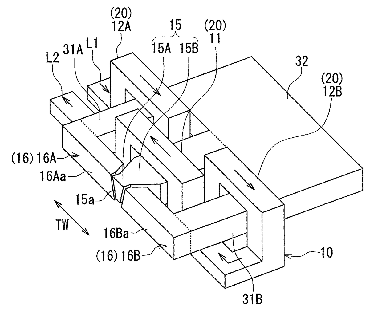
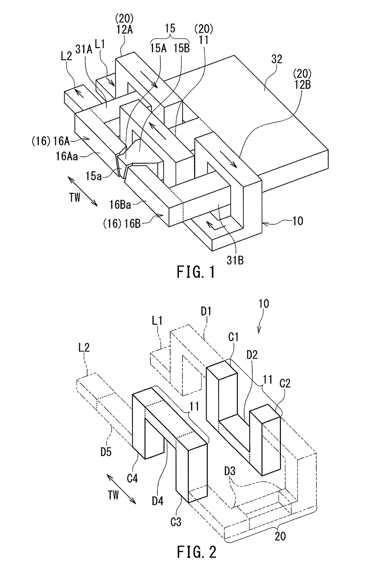
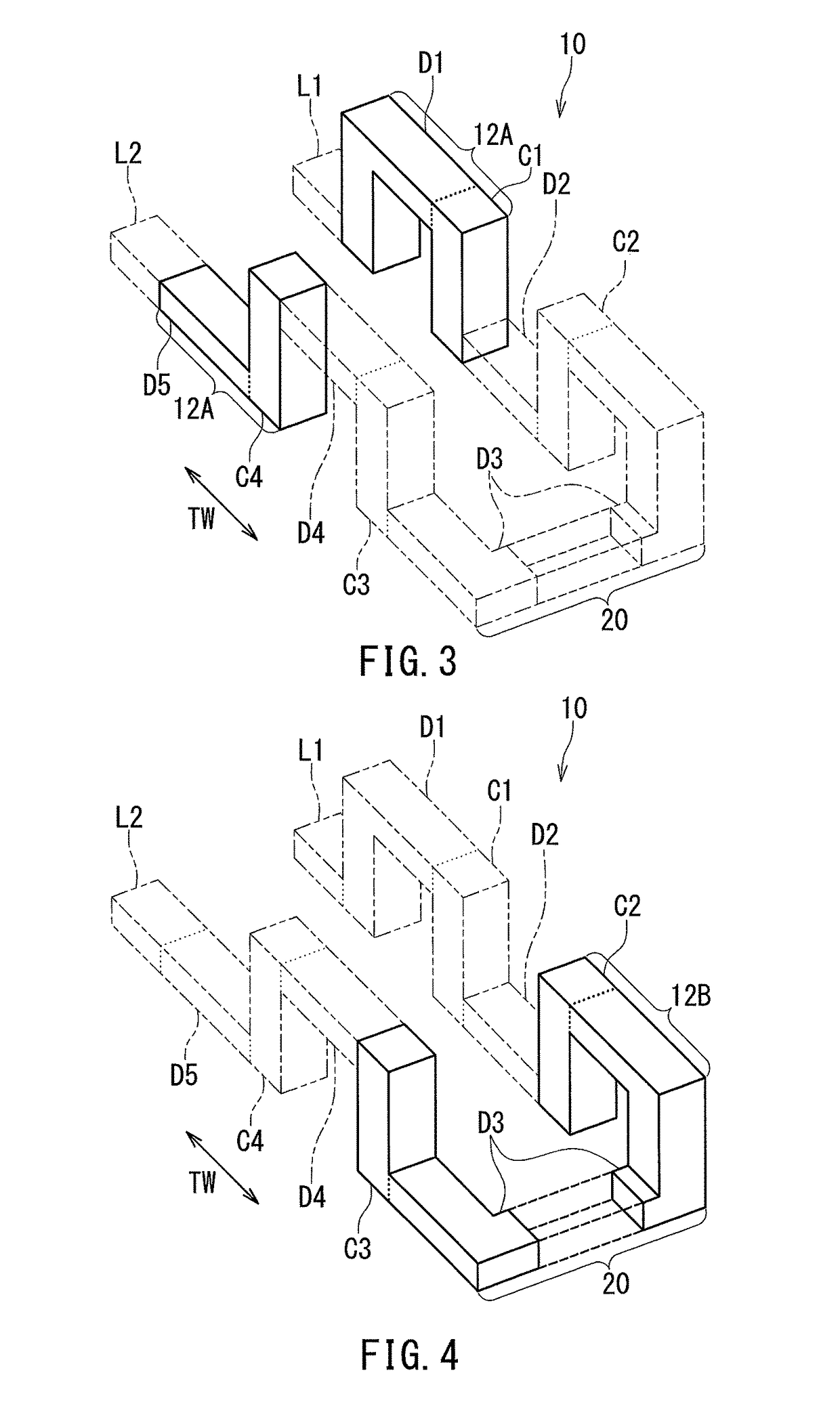
[0045]Preferred embodiments of the present invention will now be described in detail with reference to the drawings. First, reference is made to FIG. 1 to FIG. 6 to describe the configuration of a magnetic head for perpendicular magnetic recording (hereinafter simply referred to as magnetic head) according to a first embodiment of the invention. FIG. 1 is a perspective view showing the main part of the magnetic head according to the present embodiment. FIG. 2 is a perspective view showing a main coil portion of a coil of the magnetic head according to the present embodiment. FIG. 3 is a perspective view showing a first sub-coil portion of the coil of the magnetic head according to the present embodiment. FIG. 4 is a perspective view showing a second sub-coil portion of the coil of the magnetic head according to the present embodiment. FIG. 5 is a cross-sectional view of the magnetic head according to the present embodiment. The arrow labeled T in FIG. 5 indicates the direction of tr...

second embodiment

[0095]A magnetic head according to a second embodiment of the present invention will now be described with reference to FIG. 7. FIG. 7 is a perspective view showing the main part of the magnetic head according to the present embodiment. In FIG. 7, the arrow labeled TW indicates the track width direction.

[0096]The magnetic head according to the present embodiment differs from the magnetic head according to the first embodiment in the following ways. In the present embodiment, the coupling portion 32 of the first embodiment is omitted. Thus, the main pole 15 and the at least one yoke are separate from each other. In the present embodiment, in particular, the main pole 15, the first yoke 31A and the second yoke 31B are separate from each other.

[0097]In the present embodiment, the main pole 15, the first yoke 31A and the second yoke 31B are driven individually by the main coil portion 11, the first sub-coil portion 12A and the second sub-coil portion 12B, respectively. Thus, according t...

third embodiment

[0100]A magnetic head according to a third embodiment of the present invention will now be described with reference to FIG. 8 to FIG. 10. FIG. 8 is a perspective view showing the main part of the magnetic head according to the present embodiment. FIG. 9 is a cross-sectional view of the magnetic head according to the present embodiment. The arrow labeled T in FIG. 9 indicates the direction of travel of the recording medium 90. FIG. 10 is a front view showing the medium facing surface 80 of the magnetic head according to the present embodiment. In FIG. 8 and FIG. 10, the arrow labeled TW indicates the track width direction.

[0101]Now, descriptions will be given of differences of the magnetic head according to the third embodiment from the magnetic head according to the first embodiment. In the present embodiment, the end face of the write shield 16 includes a third end face portion 16Ca and a fourth end face portion 16Da in addition to the first and second end face portions 16Aa and 16...


PUM

PropertyMeasurementUnit
electric currentaaaaaaaaaa
heightaaaaaaaaaa
angleaaaaaaaaaa

Abstract

A magnetic head includes a coil, a main pole, a write shield and first and second yokes. The first and second yokes are connected to the write shield. The coil includes a main coil portion for driving the main pole, a first sub-coil portion for driving the first yoke, and a second sub-coil portion for driving the second yoke. A magnetic field produced in the main pole by the main coil portion and a magnetic field produced in each of the first and second yokes by the first and second sub-coil portions are in directions opposite to each other.

Description

BACKGROUND OF THE INVENTION[0001]1. Field of the Invention[0002]The present invention relates to a magnetic head for perpendicular magnetic recording for use to write data on a recording medium by means of a perpendicular magnetic recording system.[0003]2. Description of the Related Art[0004]The recording systems of magnetic read / write apparatuses include a longitudinal magnetic recording system in which the magnetization of signals is directed along the plane of a recording medium (the longitudinal direction), and a perpendicular magnetic recording system in which the magnetization of signals is directed perpendicular to the plane of a recording medium. It is known that the perpendicular magnetic recording system is harder to be affected by thermal fluctuation of the recording medium and capable of providing higher linear recording density, compared with the longitudinal magnetic recording system.[0005]Magnetic heads for perpendicular magnetic recording typically have, like those f...

Claims


Application Information

Patent Timeline
Patent Type & Authority Patents(United States)
IPC IPC(8): G11B5/127G11B5/39G11B5/17
CPCG11B5/3912G11B5/1278G11B5/17G11B5/3123
Inventor SASAKI, YOSHITAKASATO, KAZUKIITO, HIROYUKITANEMURA, SHIGEKIOKADA, MASAKAZU
Owner HEADWAY TECH INC
Why Eureka
Try Eureka