Control device for an asynchronous machine and method for operating an asynchronous machine

a control device and asynchronous machine technology, applied in the direction of electronic commutation motor control, process and machine control, instruments, etc., can solve the problem of inability to field-oriented closed-loop control of asynchronous machines, achieve significant faster magnetization, prevent undesired torque, and increase the functional reliability of asynchronous machines

Inactive Publication Date: 2016-04-14
ROBERT BOSCH GMBH
View PDF5 Cites 0 Cited by
  • Summary
  • Abstract
  • Description
  • Claims
  • Application Information

AI Technical Summary

Benefits of technology

[0009]As a result of the early determination of the correct rotor field angle during the buildup of the rotor field, the asynchronous machine can already be actuated early in a closed-loop controlled operating mode during the magnetization phase. It is therefore also already possible to set a predefined torque precisely during the magnetization phase.
[0010]A further advantage is that by virtue of the early closed-loop controlled operation of the asynchronous machine, the asynchronous machine can be magnetized significantly more quickly.
[0011]An additional advantage is that the asynchronous machine can already be operated with a predefined torque during the magnetization phase. This prevents an undesired torque occurring owing to an unknown rotor field angle. This increases the functional reliability of the asynchronous machine
[0013]In a further embodiment of the control device according to the invention, the rotor field angle detector also comprises a device for generating voltage pulses, wherein the device is configured to apply voltage pulses to stator phases of the asynchronous machine; a current-measuring device which is configured to measure a current response to the applied current pulses in the stator phases; and a device for determining a rotor field angle which is configured to determine the rotor field angle on the basis of the measured current responses. By applying voltage pulses to the asynchronous machine and by means of a subsequent evaluation of the current responses in the stator phases it is possible to determine the current rotor field angle precisely in encoder-free fashion without additional sensors.

Problems solved by technology

In this open-loop controlled operating mode, field-oriented closed-loop control of the asynchronous machine is not possible.

Method used


Image

  • Control device for an asynchronous machine and method for operating an asynchronous machine
  • Control device for an asynchronous machine and method for operating an asynchronous machine
  • Control device for an asynchronous machine and method for operating an asynchronous machine

Examples


Embodiment Construction

[0024]FIG. 1 shows a schematic illustration of a control device 1 for an asynchronous machine 2 as forms the basis of an embodiment of the present invention. The asynchronous machine 2 can be here any asynchronous machine, in particular an asynchronous motor with short-circuit rotor. The asynchronous machine is preferably a three-phase asynchronous machine. Such an asynchronous machine comprises a rotatably mounted rotor in the interior and an exterior fixed stator. A plurality of stator phases which are offset equidistantly from one another are let into the stator here. These stator phases are embodied, for example, as wire windings.

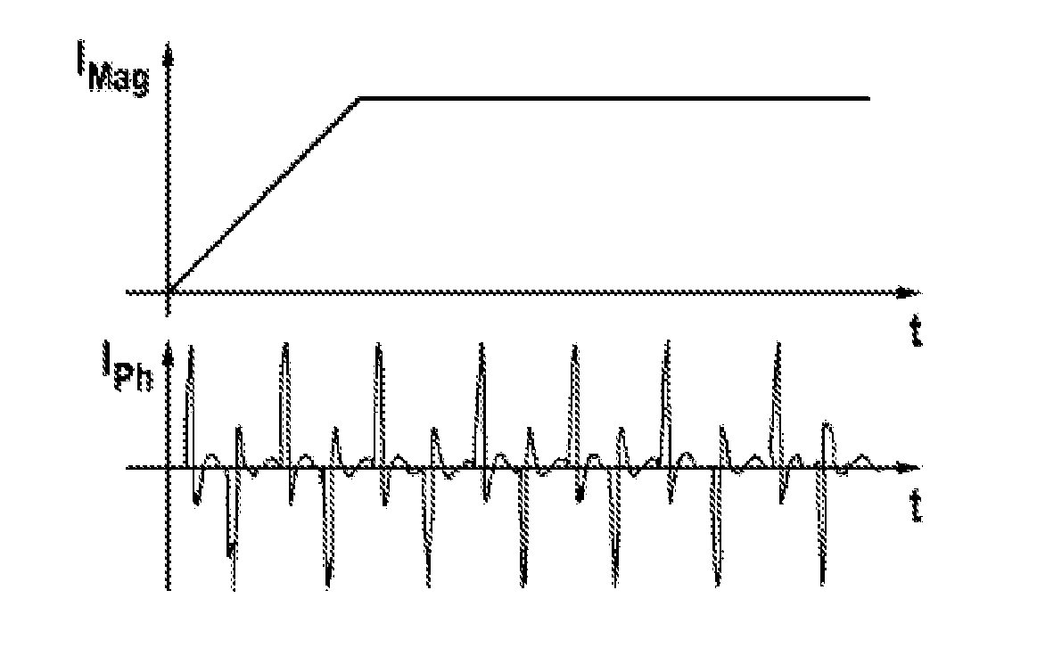
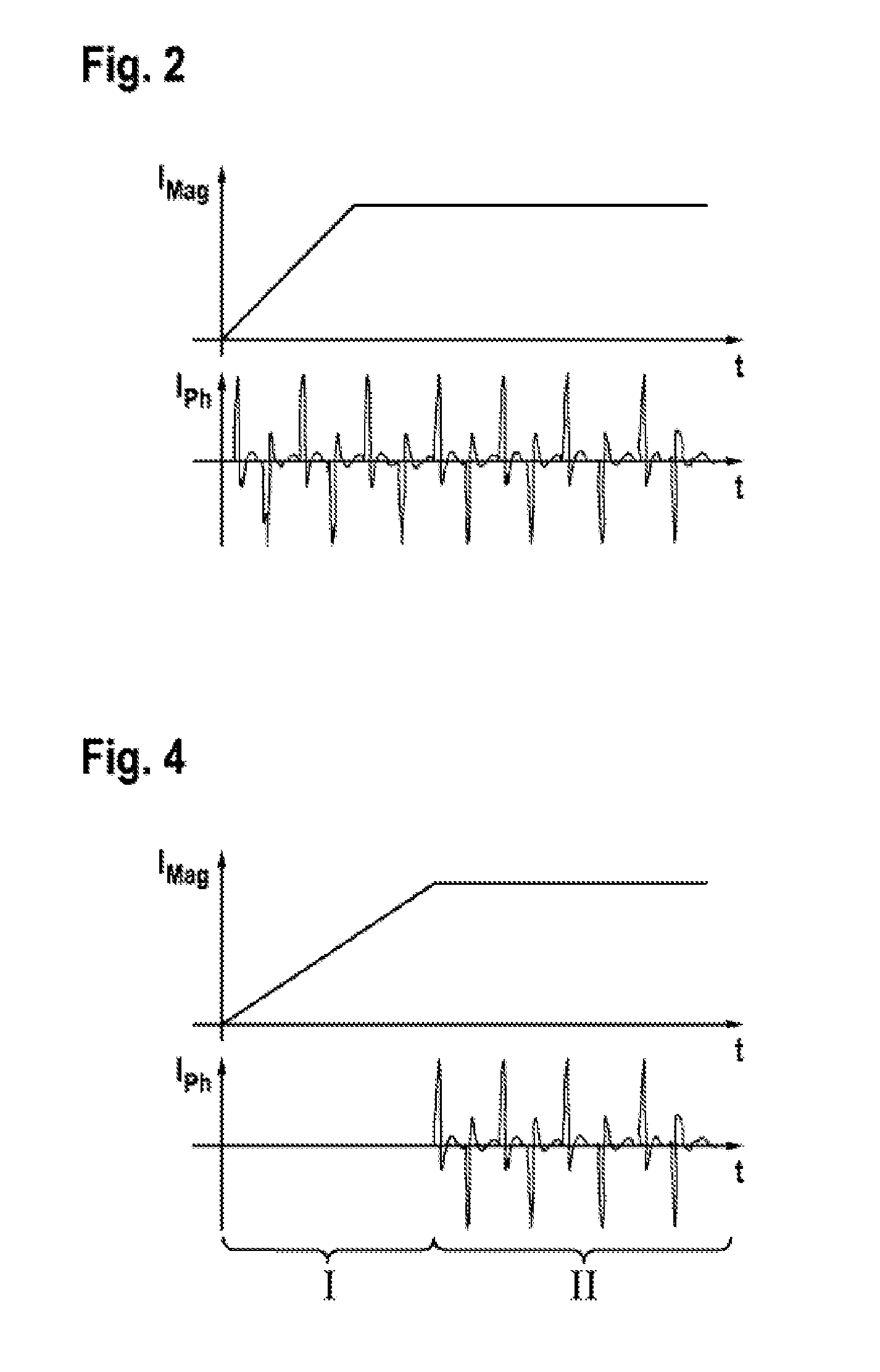
[0025]Since the rotor voltage is induced by means of the stator magnetic field in asynchronous machines, there is firstly no rotor field in the non-energized state in asynchronous machines. This rotor field firstly has to be built up during a magnetization phase. Conventional determination of the rotor field angle by measuring the inductivity is therefo...


PUM


Abstract

The present invention provides a method and a device to determine the rotor field angle of an asynchronous machine even during the magnetising phase, in which the rotor field of a rotor of the asynchronous machine is built up. The asynchronous machine can then be actuated in a controlled operating mode even during the magnetising phase. The startup properties of the asynchronous machine can thus be improved, the magnetising phase of the asynchronous machine is shortened and it is possible to set a desired torque even during the magnetising phase.

Description

BACKGROUND OF THE INVENTION[0001]The present invention relates to a control device for an asynchronous machine and a method for operating an asynchronous machine in a magnetization phase.[0002]In order to be able to set a required torque precisely in an asynchronous machine, it is necessary, given field-oriented control of the asynchronous machine, to know the rotor field angle precisely. The determination of a rotor field angle in an asynchronous machine can be carried out here either by means of additional angle sensors or by means of an encoder-free method. When an additional angle encoder is used to determine the rotor field angle, additional sensors have to be attached to the rotation axis of the asynchronous machine, which sensors output a signal, which can be evaluated, as a function of the angle position of the rotor axis. In an alternative, encoder-free determination of the rotor field angle, the rotor position is determined by evaluating phase currents and voltages of the ...

Claims


Application Information

Patent Timeline
Patent Type & Authority Applications(United States)
IPC IPC(8): H02P23/14G05B17/02
CPCH02P23/14H02P2207/01G05B17/02H02P6/185H02P2203/11H02P21/18
Inventor BRAUN, MARTINDIETRICH, SIMON
Owner ROBERT BOSCH GMBH
Why Eureka
Try Eureka