Circuit arrangement and method for Insulation monitoring for inverter applications

Active Publication Date: 2008-04-10
SCHMIDHAUSER AG
View PDF11 Cites 61 Cited by
  • Summary
  • Abstract
  • Description
  • Claims
  • Application Information

AI Technical Summary

Benefits of technology

[0013] It is therefore desirable to provide a method and a device for the insulation monitoring

Problems solved by technology

An insulation monitoring must detect this first fault, before a second, potentially dangerous fault occurs.
With IT-networks with electrical (clocked) drives, fault currents arise due to the relocation of charge carriers in the cable and motor capacitances, and these fault currents behave similarly to fault currents that are due to insulation defects.
Conventional insulation testing apparatus are interfered with on account of this, which leads to misleading error messages with regard to the condition of the insulation.
The setting of the warning limits and the fault limits is rendered more difficult and partly rendered impossible, due to the dependency of these capacitive fault currents on the number of drives, their momentary operating conditions, and on the manner in which the cables are laid.
Making this more difficult is also the fact that these capacitive fault currents may change on account of the aging of the insulation, dirt and humidity, so that warning limits and fault limits which were once set in an optimal manner, must also be reset later, in order to avoid misleading error messages.
As a rule, additional circuit parts are incorporated for this, which in the case of a fault, may themselves lead to a loss of insulation, which increases the failure rate of the complete system.
Insulation defects may occur ev

Method used


Image

  • Circuit arrangement and method for Insulation monitoring for inverter applications
  • Circuit arrangement and method for Insulation monitoring for inverter applications
  • Circuit arrangement and method for Insulation monitoring for inverter applications

Examples


Embodiment Construction

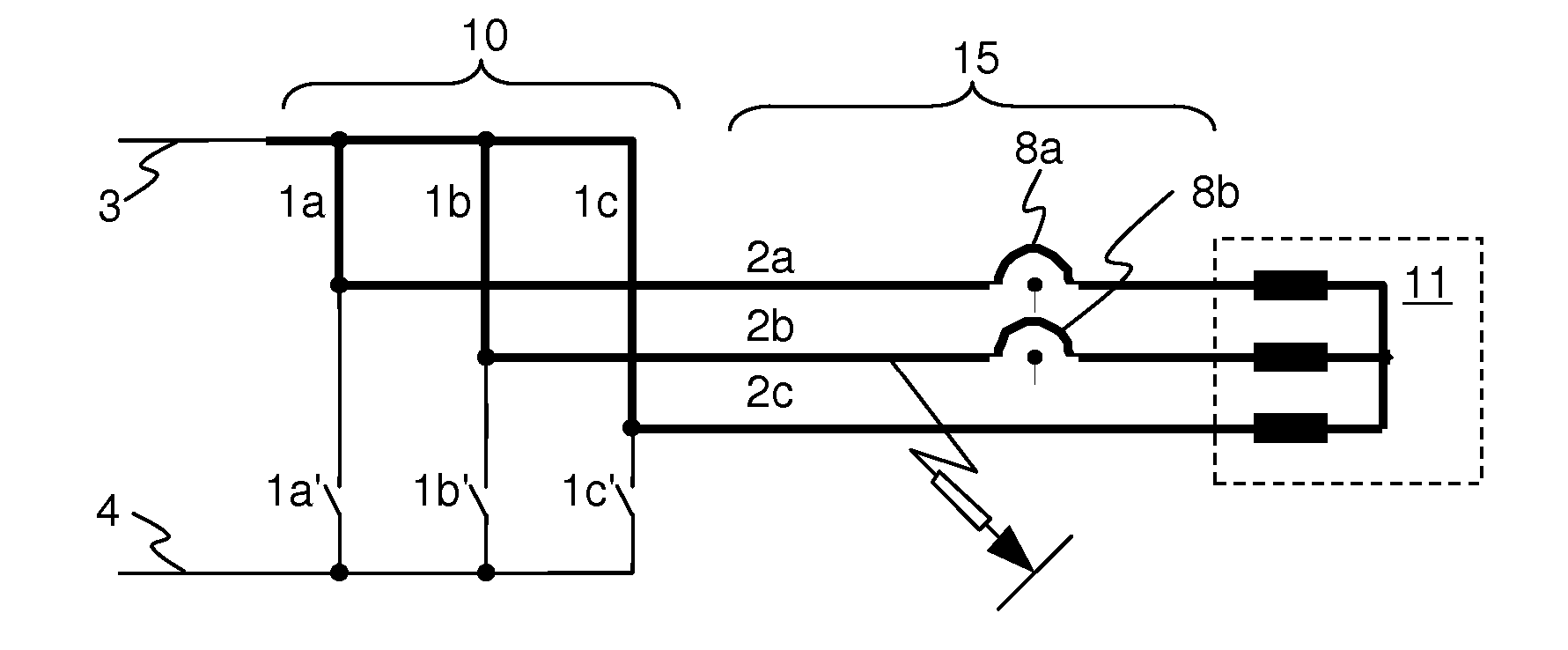
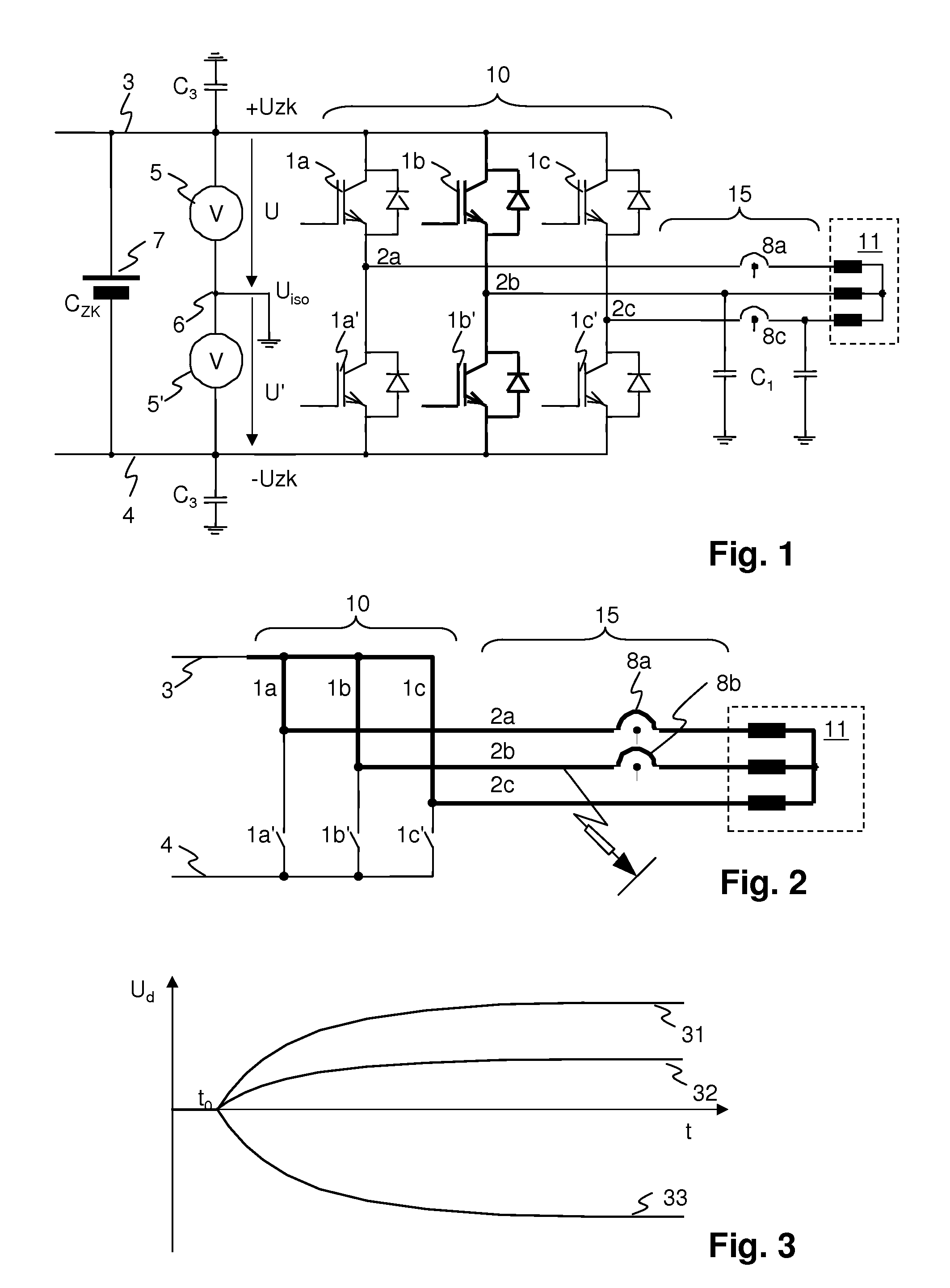
[0072]FIG. 1 shows an inverter arrangement. An intermediate circuit 7 with an intermediate circuit (or CD link) capacitance CZK is fed by a source (not shown), for example an active or passive rectifier (directly or via a direct current network) or a battery, which may be connected directly or via a DC voltage controller. A rectifier is typically fed by a transformer or a generator. A neutral point 6 of the intermediate circuit 7 is electrically connected to earth, a vehicle chassis and / or to housing parts of the apparatus in the IT network. The intermediate circuit 7 comprises a positive branch 3 whose voltage +UZK with respect to the neutral point 6 may be measured by a first branch voltage measurement 5, and a negative branch 4 whose voltage −UZK may be measured by a second branch voltage measurement 5′. An inverter 10 is formed in the known manner by way of electronic power switches, which collectively are indicated with the reference numeral 1. A first group of these switches 1...


PUM


Abstract

An inverter application comprises at least one apparatus fed by an inverter (10). The determining of insulation defects is effected by way of a differential voltage of part voltages (U, U′) of an intermediate circuit (7) or the ratio of one of these part voltages (U, U′) to the total voltage of an intermediate circuit, and by way of an operating condition of the inverter (10). The monitoring of the insulation is carried out only with the means (1a, 1b, 1c, 1a′, 1b′, 1c′, 5, 5′) which are present in the inverter (10) in any case. The operating condition is set as a particular switch position in the inverter (10) by an insulation monitoring system. Alternatively, the operating condition is, while the inverter is on-line or in operation, transferred from the inverter control (9) to an insulation monitoring system for improving the quality of the monitoring.

Description

[0001] The invention relates to the field of power electronics. It relates in particular to a method and to a device for insulation monitoring for inverter applications. BACKGROUND [0002] In an IT-system (French IsoléTerre) or an IT-network, conductive housings of the devices are earthed, but not the star point of a feeding transformer. Thus (with small networks), no dangerous touch voltage occurs given an insulation fault between a conductor of the network and the housing or earth. An insulation monitoring must detect this first fault, before a second, potentially dangerous fault occurs. [0003] With IT-networks with electrical (clocked) drives, fault currents arise due to the relocation of charge carriers in the cable and motor capacitances, and these fault currents behave similarly to fault currents that are due to insulation defects. Conventional insulation testing apparatus are interfered with on account of this, which leads to misleading error messages with regard to the condit...

Claims


Application Information

Patent Timeline
IPC IPC(8): G01R31/14G01R31/08
CPCG01R27/18G01R31/024H02H7/1227G01R31/42G01R31/1227G01R31/52
Inventor ITTEN, ALEXTHUR, PETER
Owner SCHMIDHAUSER AG
Why Eureka
Try Eureka