Imaging forming apparatus

a technology of image forming apparatus and forming apparatus, which is applied in the direction of lighting and heating apparatus, printing, instruments, etc., can solve the problems of difficult design of such optical systems, deterioration of extinction ratio of entire image-forming optical systems, and inability to meet the requirements of magnification power, so as to facilitate the design of magnified-image-forming optical systems. , to prevent the effect of deterioration of extinction ratio
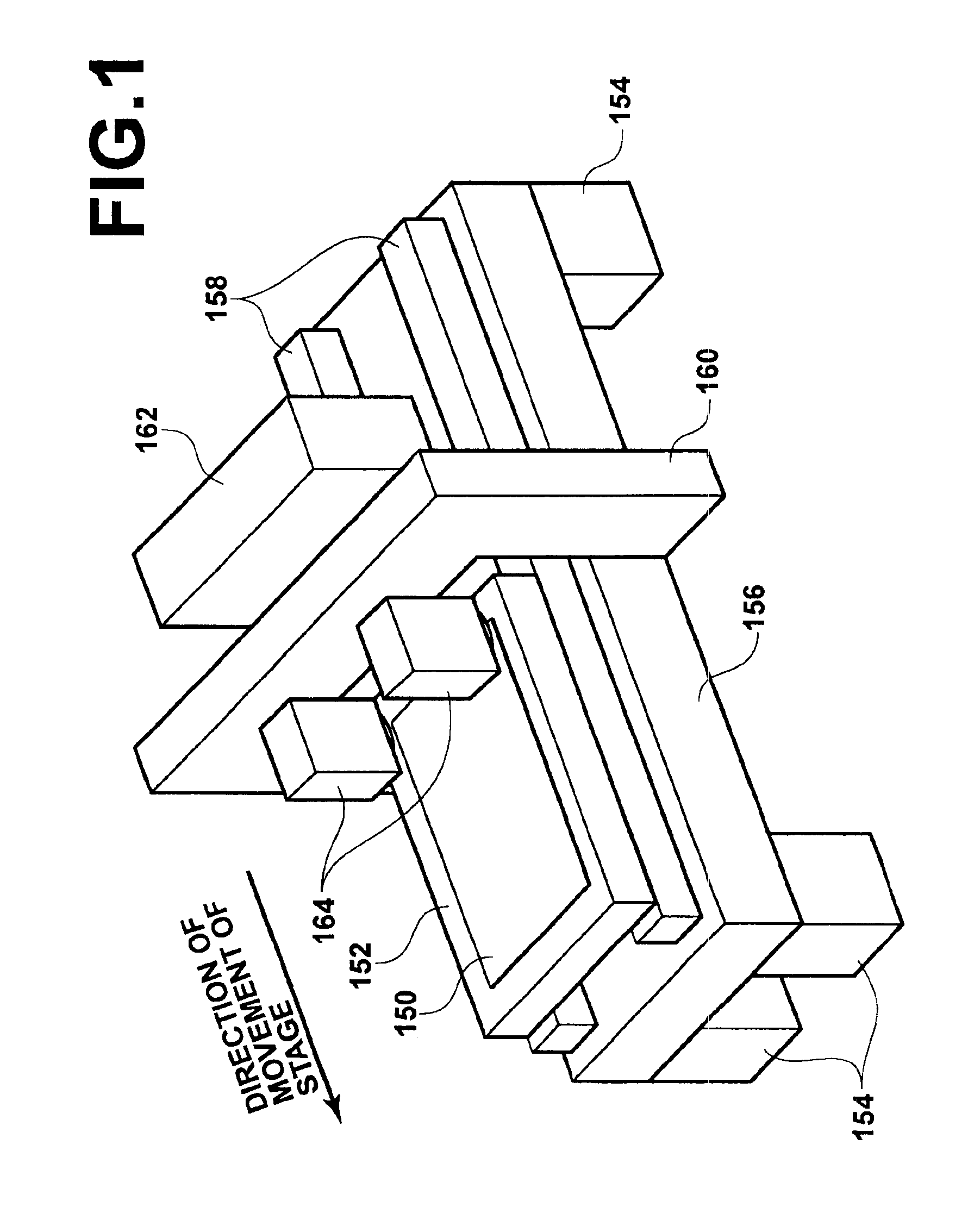
Inactive Publication Date: 2005-04-05
FUJIFILM CORP +1
View PDF9 Cites 65 Cited by
  • Summary
  • Abstract
  • Description
  • Claims
  • Application Information

AI Technical Summary

Benefits of technology

A first object of the present invention is to provide an image forming apparatus which contains a magnified-image-forming optical system realized by a combination of image-forming optical systems and a microlens array, prevents deterioration of the extinction ratio caused by distortion aberration in the magnified-image-forming optical system, and facilitates designing of the magnified-image-forming optical system.
A second object of the present invention is to provide an image forming apparatus having a construction in which a microlens array and an aperture array are combined, and being able to precisely set a relative position between the microlens array and the aperture array in the direction of an optical axis.
According to the first aspect of the present invention, both of the first and second image-forming optical systems are a magnified-image-forming optical system, and a desired magnification ratio is obtained by the product of the magnification powers of the first and second image-forming optical systems. Therefore, it is possible to make each of the magnification powers of the first and second image-forming optical systems small. Thus, it is possible to prevent deterioration of distortion characteristics which occurs when the magnification power of the first image-forming optical system is great, and achieve a satisfactory extinction ratio. In addition, it is possible to avoid the aforementioned problems which occur when the magnification power of the second image-forming optical system is great, and facilitate designing of the image-forming optical systems.
According to the second aspect of the present invention, one of the microlens array and the aperture array has at least one protrusion toward the other of the microlens array and the aperture array, the at least one protrusion has a predetermined height in the direction of the optical axis, and the relative position between the microlens array and the aperture array is set by the other of the microlens array and the aperture array abutting the at least one protrusion of one of the microlens array and the aperture array. Therefore, when the at least one protrusion is produced so as to have an appropriate height as designed, it is possible to precisely set the relative position between the microlens array and the aperture array in the direction of the optical axis so that apertures of the aperture array are located at positions at which a plurality of portions of light from microlenses constituting the microlens array converge, respectively. Thus, it is possible to prevent deterioration in the extinction ratio due to stray light, and increase the light utilization efficiency.
According to the third aspect of the present invention, the relative position between the microlens array and the aperture array in the direction of the optical axis is set by joining the microlens array and the aperture array together through a spacer having a predetermined thickness. Therefore, when the spacer is produced so as to have an appropriate thickness as designed, it is possible to precisely set the relative position between the microlens array and the aperture array in the direction of the optical axis so that apertures of the aperture array are located at positions at which a plurality of portions of light from microlenses constituting the microlens array converge, respectively. Thus, it is possible to prevent deterioration in the extinction ratio due to stray light, and increase the light utilization efficiency.

Problems solved by technology

When an attempt is made to achieve a great magnification ratio by using first and second image-forming optical systems as mentioned above in a construction in which the first and second image-forming optical systems and a microlens array are combined as above, some problems can occur depending on magnification powers set in the first and second image-forming optical systems.
Therefore, the entire image-forming optical system is sensitive to errors, and designing such an optical system is not easy.
If the error in the position of the aperture array is great, problems occur.
For example, the extinction ratio deteriorates due to entrance of stray light, or increase in the amount of light eclipsed by the circumferences of the apertures reduces the light utilization efficiency.

Method used


Image

  • Imaging forming apparatus
  • Imaging forming apparatus
  • Imaging forming apparatus

Examples


first embodiment

Operations of First Embodiment

Operations of the above image exposure apparatus according to the first embodiment are explained below.

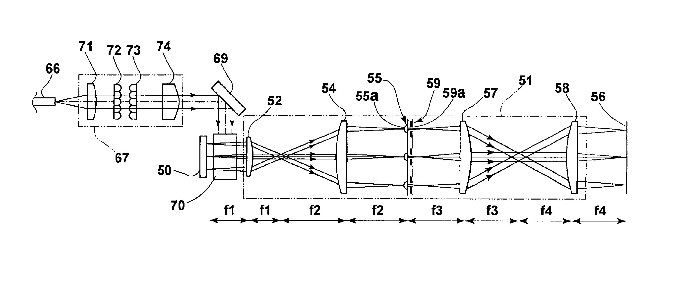
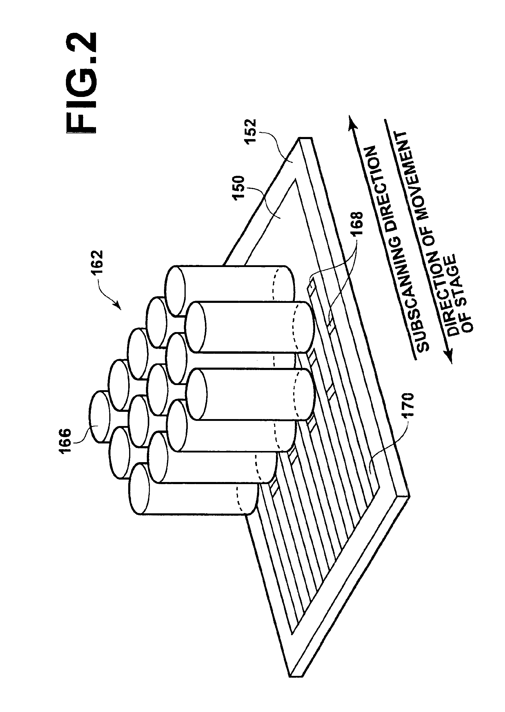
In each of the exposure heads 166 in the scanner 162, divergent laser beams B1 through B7 emitted from the GaN-based laser-diode chips LD1 through LD7 in each of the optically-multiplexing laser-light sources 64 (constituting the fiber-array light source 66) are respectively collimated by the corresponding collimator lenses 11 through 17. The collimated laser beams B1 through B7 are collected by the condensing lens 20 so as to converge on the light-entrance end face of the core 30a of the aforementioned multimode optical fiber 30 in the optically-multiplexing laser-light source. In this example, an optical condensing system is constituted by the collimator lenses 11 through 17 and the condensing lens 20, and an optical multiplex system is constituted by the optical condensing system and the multimode optical fiber 30. Thus, the laser beams B1 through B...

second embodiment

The second embodiment of the present invention is explained below with reference to FIG. 22, which is a schematic side view of an assembly of a microlens array and an aperture array in the second embodiment of the present invention. In FIG. 22, elements which are equivalent to corresponding elements in FIG. 19 are denoted by the same reference numerals as the corresponding elements in FIG. 19, and the explanations on the equivalent elements are not repeated here.

In the construction of FIG. 22, a substrate portion 59b′ of an aperture array 59′ has a simple planar shape. The other portions of the aperture array 59′ are identical to the corresponding portions of the aperture array 59 in FIG. 19. The aperture array 59′ and a microlens array 55 are combined through a spacer 61 having a predetermined thickness H′.

When the spacer 61 in the above construction is manufactured so as to have an appropriate thickness as designed, it is possible to precisely set the relative position between the...


PUM

PropertyMeasurementUnit
flatnessaaaaaaaaaa
focal lengthsaaaaaaaaaa
focal lengthaaaaaaaaaa

Abstract

In an image forming apparatus: pixel portions of a spatial light-modulation element are two-dimensionally arranged, and individually modulate portions of light applied to the spatial light-modulation element, according to control signals; a first image-forming optical system is arranged in optical paths of the portions of the light modulated by the pixel portions; a microlens array is arranged in a vicinity of an image-forming plane of the first image-forming optical system, and has microlenses arranged in correspondence with the pixel portions, respectively; and a second image-forming optical system is arranged in optical paths of the portions of the light which have passed through the microlenses, and forms on a predetermined surface an image represented by the portions of the light-modulated by the spatial light-modulation element. Each of the first and second image-forming optical systems forms an image with a magnification power greater than one.

Description

BACKGROUND OF THE INVENTION1. Field of the InventionThe present invention relates to an image forming apparatus which modulates light with a spatial light-modulation element, and forms an image on a predetermined surface by using an image-forming optical system, where the image is represented by the light modulated by the spatial light-modulation element.2. Description of the Related ArtThe following documents (1) to (3) disclose information related to the present invention.(1) Japanese Unexamined Patent Publication No. 2001-305663(2) Japanese Unexamined Patent Publication No. 2001-21830(3) Akito Ishikawa, “Reduction of Developing Time by Maskless Exposure and Application to Mass Production,” Electronics Packing Technology (Electronics Jissou Gijutsu), Vol. 18, No. 6, (2002) PP. 74-79, Gicho Publishing & Advertising Co., Ltd. (Kabushiki Kaisha Gijutsu Chosa Kai).In some conventionally known image forming apparatuses, light is modulated by a spatial light-modulation element, and an i...

Claims


Application Information

Patent Timeline
Patent Type & Authority Patents(United States)
IPC IPC(8): G02B26/08G03F7/20
CPCG02B26/0841G03F7/70291G03F7/70275G03F7/7005
Inventor ISHIKAWA, HIROMINAGANO, KAZUHIKO
Owner FUJIFILM CORP
Why Eureka
Try Eureka