Control device for an asynchronous machine and method for driving an asynchronous machine

A control device and motor controller technology, which is applied in the direction of controlling electromechanical brakes, controlling electromechanical transmission devices, controlling generators, etc., can solve the problems of inability to control asynchronous machines in a field-oriented manner, and achieve the effect of improving functional reliability

Active Publication Date: 2018-10-09
ROBERT BOSCH GMBH
View PDF6 Cites 0 Cited by
  • Summary
  • Abstract
  • Description
  • Claims
  • Application Information

AI Technical Summary

Problems solved by technology

In this controlled work, asynchronous machines cannot be controlled field-oriented

Method used


Image

  • Control device for an asynchronous machine and method for driving an asynchronous machine
  • Control device for an asynchronous machine and method for driving an asynchronous machine
  • Control device for an asynchronous machine and method for driving an asynchronous machine

Examples


Embodiment Construction

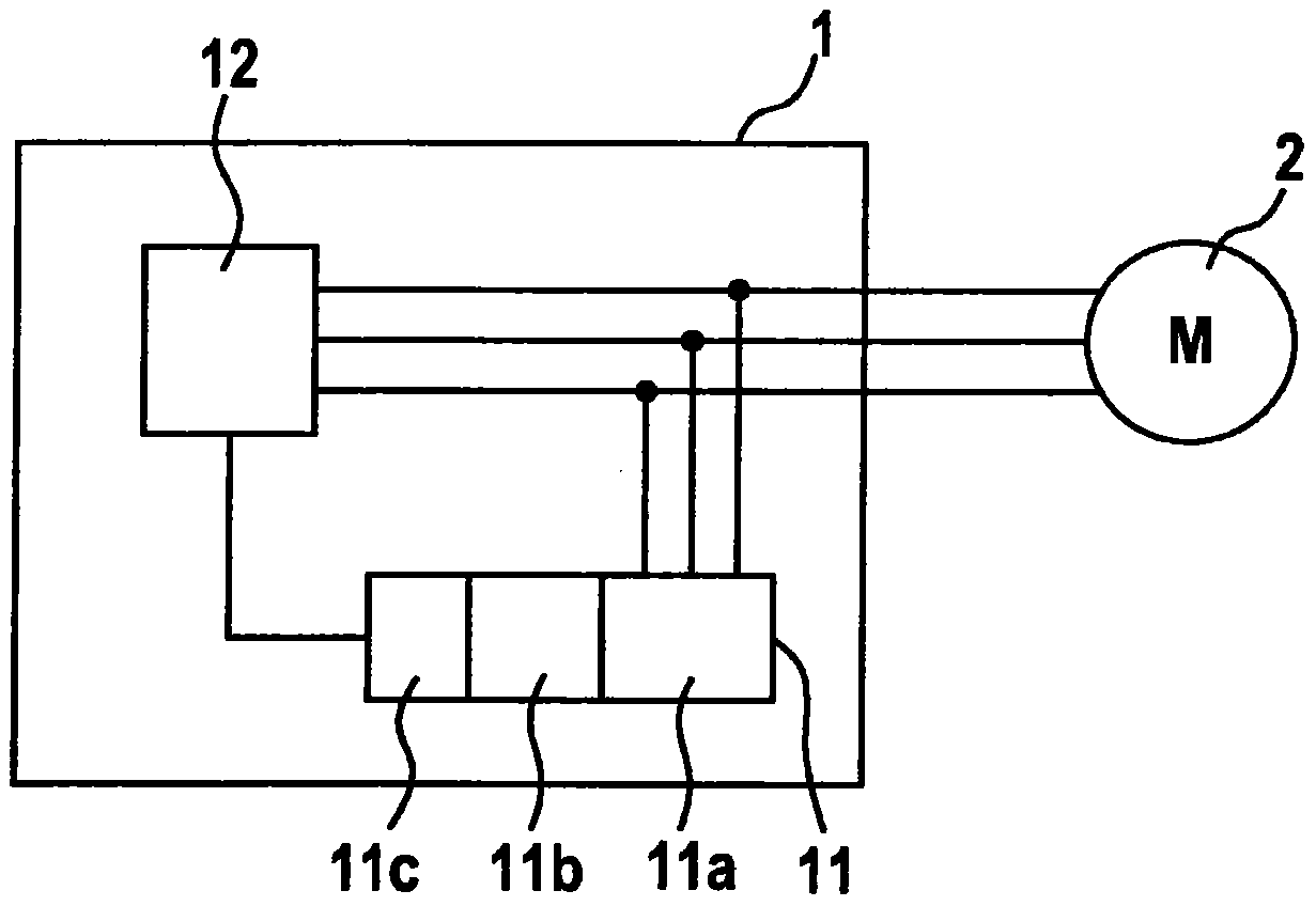
[0024] figure 1 Shown is a schematic diagram of a control device 1 for an asynchronous machine 2 , for example, according to an embodiment of the invention. The asynchronous machine 2 can here be any asynchronous machine, in particular an asynchronous machine with a squirrel-cage rotor. The asynchronous machine is preferably a three-phase AC asynchronous machine. Such an asynchronous machine comprises internally a rotatably mounted rotor and externally a stationary stator. In this case, a plurality of stator strands that are equally spaced apart from one another are introduced into the stator. These stator strands are, for example, winding wires.

[0025] Since the asynchronous motor induces the rotor voltage through the stator magnetic field, the asynchronous motor does not initially have a rotor field when it is not powered. The rotor field must only be established during the magnetization phase. It is therefore initially not possible to determine the rotor field angle ...


PUM


Abstract

The invention proposes a method and a device for ascertaining the rotor field angle of an asynchronous machine already during the magnetization phase in which the rotor field of the asynchronous machine rotor is to be established. The asynchronous machine can then be controlled in controlled work already during the magnetization phase. As a result, the starting behavior of the asynchronous machine can be improved, the magnetization phase of the asynchronous machine is shortened and the desired torque can already be generated during the magnetization phase.

Description

technical field [0001] The invention relates to a control device for an asynchronous machine and a method for driving an asynchronous machine in a magnetization phase. Background technique [0002] In order to be able to precisely generate the required torque in an asynchronous machine, precise knowledge of the rotor field angle is required during the field-oriented control of the asynchronous machine. The ascertainment of the rotor field angle in asynchronous machines can be carried out either by means of additional angle sensors or by means of a transmitter-less method. If additional angle transmitters are used to determine the rotor field angle, additional sensors must be mounted on the shaft of the asynchronous machine, which output signals that can be evaluated as a function of the angular position of the shaft. If instead the rotor field angle is ascertained without a transmitter, the rotor position is determined by dividing the phase currents and voltages of the asyn...

Claims


Application Information

Patent Timeline
Patent Type & Authority Patents(China)
IPC IPC(8): H02P6/185H02P21/18
CPCH02P6/185H02P2203/11H02P2207/01H02P21/18G05B17/02H02P23/14
Inventor M·布劳恩S·迪特里希
Owner ROBERT BOSCH GMBH
Why Eureka
Try Eureka