Torque tool, socket selection mechanism, and methods of use

a technology of socket selection and torque tool, which is applied in the direction of underwater equipment, instruments, and borehole/well accessories, etc., can solve the problems of subsea component failure or damage, difficulty in retrieving subsea components for repair or replacement, and high cos

Active Publication Date: 2016-12-01
FORUM ENERGY TECH UK
View PDF3 Cites 3 Cited by
  • Summary
  • Abstract
  • Description
  • Claims
  • Application Information

AI Technical Summary

Benefits of technology

[0007]It is another object of an aspect of the present invention to provide a robust, reliable and compact torque tool suitable for deployment subsea which is capable of changing socket sizes quickly such that the correct torque can be reliably applied to a subsea structure component.
[0057]In one embodiment, rotation of the rotary actuator in a first direction effects axial movement of at least one of the plurality of drive heads between an operative position and an inoperative position. Rotation of the rotary actuator in a second direction may effect axial movement of at least one of the plurality of drive heads between an inoperative position and an operative position.

Problems solved by technology

The component may fail or become damaged if the torque applied to it by a torque tool is excessive.
The retrieval of the subsea component for repair or replacement can be difficult and expensive.
However, this method can be cumbersome and time-consuming.
However, spring loaded nested sockets have the disadvantage that when the torque tool socket is docked onto a subsea structure component, it is not clear which socket size is being used.
If an incorrect socket size is used it may result in the wrong value of torque being applied to the subsea structure component and result in significant damage to the subsea structure and the torque tool.

Method used


Image

  • Torque tool, socket selection mechanism, and methods of use
  • Torque tool, socket selection mechanism, and methods of use
  • Torque tool, socket selection mechanism, and methods of use

Examples


Embodiment Construction

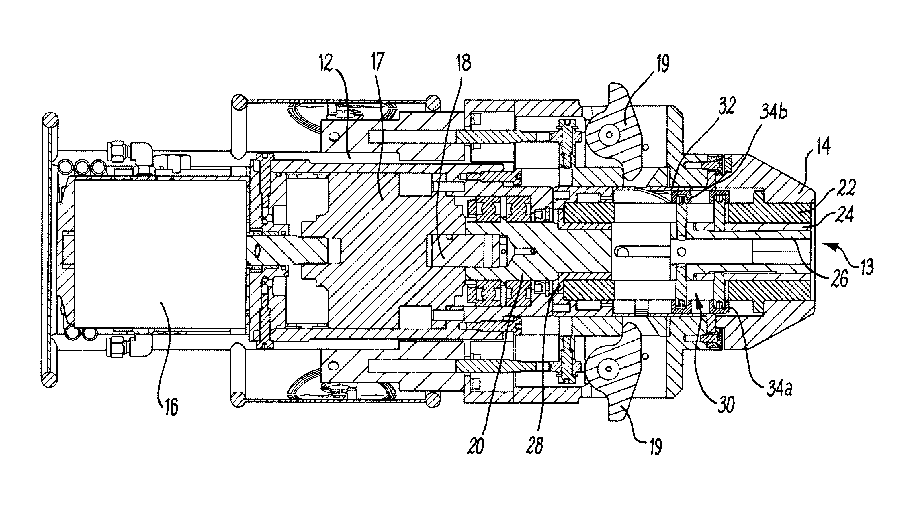
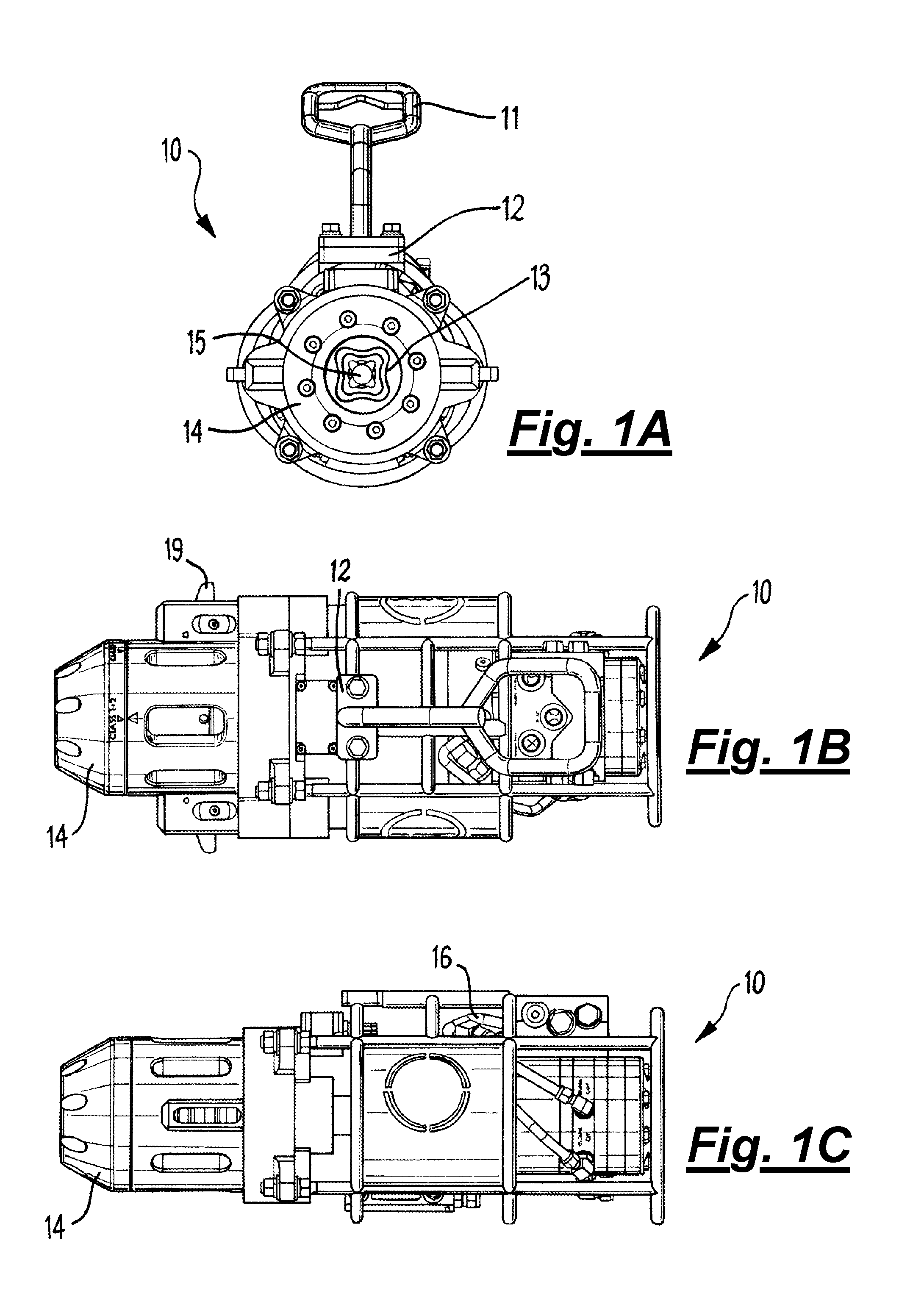
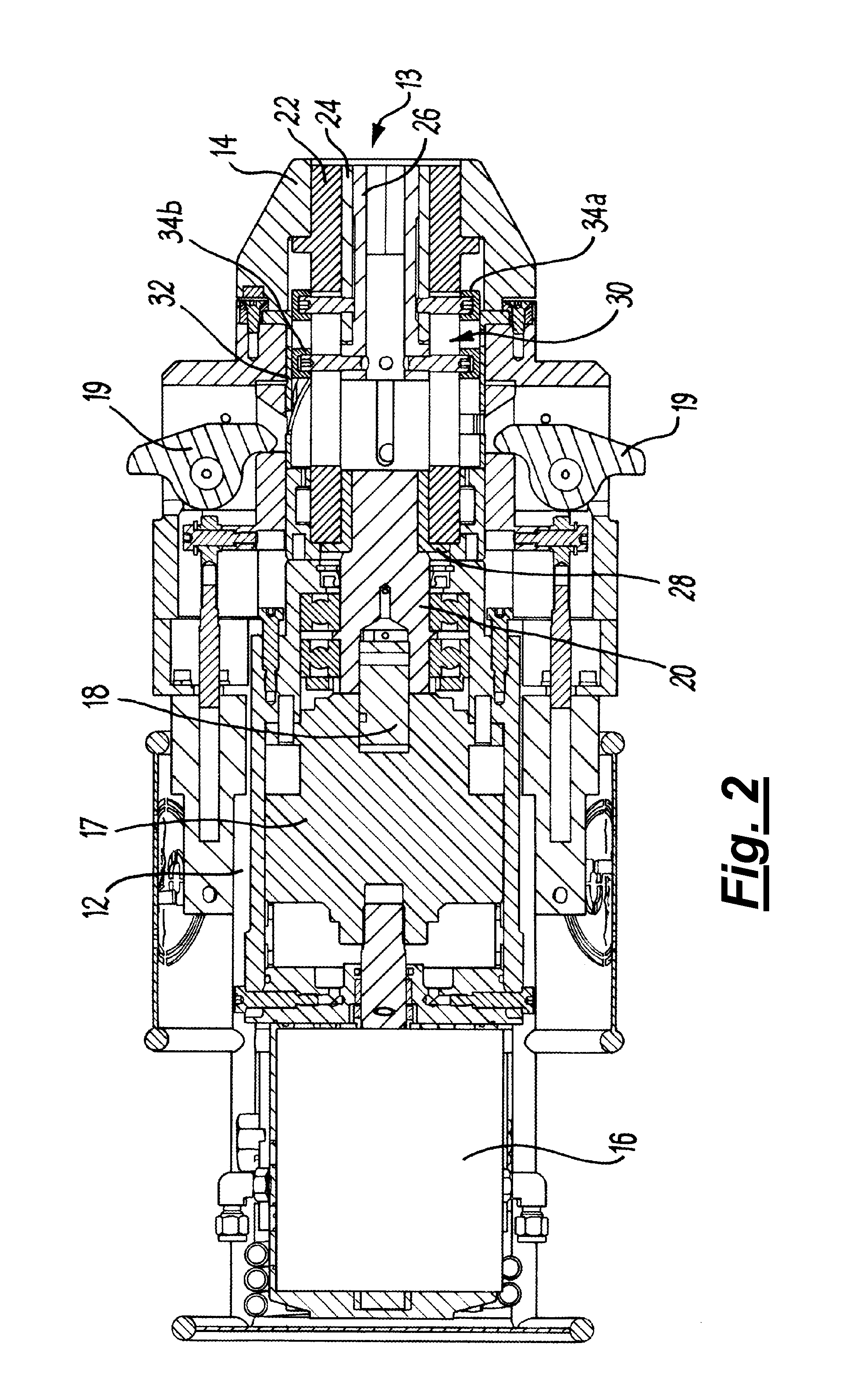
[0110]FIGS. 1A, 1B and 1C show a torque tool 10 according to a first embodiment of the invention, shown from front, plan and side views respectively. The tool 10 is configured to apply a torque to a rotatable component of a subsea structure. The tool 10 has a handle 11 attached to the main body 12. At one end of the tool 10 is a rotatable socket assembly 13 surrounded by a nose cone 14. The socket assembly 13 is connected to a drive shaft 15 which is driven by a motor assembly 16, which in this embodiment is a gerotor type of hydraulic motor. The sockets are drive heads for this particular torque tool, although it will be appreciated that the principles of the invention extend to other drive head types.

[0111]The socket assembly 13 is designed to engage with a rotatable component of a subsea structure. Wing members 19 engage the subsea structure to hold the tool onto the interface and lock the tool into position. The motor assembly generates an output torque which is transferred to t...


PUM


Abstract

The invention provides a subsea torque tool (10) for a subsea vehicle system (such as an ROV), a drive head selection mechanism (30), and a method of use. The tool comprises a tool housing and a plurality of torque drive heads (22, 24, 26). The drive mechanism (17, 18, 20, 28) is operable to rotate the plurality of torque drive heads, and the drive head selection mechanism is used to select a drive head to impart a torque to a subsea device. The drive head selection mechanism comprises a rotary actuator (14, 32), and rotation of the rotary actuator effects axial movement of at least one of the plurality of drive heads between an operative position and an inoperative position. In another aspect, the drive head selection mechanism comprises an actuator operable from the exterior of the torque tool. In a preferred embodiment, the drive heads are sockets (22, 24, 26), and the selection mechanism comprises a rotary actuator and a cam mechanism. The at least one socket may be permitted to rotate with respect to the cam mechanism when a driving torque is applied to the torque sockets.

Description

[0001]The present invention relates to a torque tool and a method of use, and in particular to a torque tool used in subsea applications for the actuation and operation of subsea equipment. Aspects of the invention relate to torque tools operable by subsea vehicles such as Remotely Operated Vehicles (ROVs). A particular aspect of the invention relates to a torque drive head selection mechanism for a subsea torque tool.BACKGROUND TO THE INVENTION[0002]Subsea torque tools are required to perform a range of tasks on subsea infrastructure and equipment, for example applying torque to actuate rotating components of valves, or to lockdown or release clamps on equipment for the oil and gas industry. Typically, these rotating components are designed to be actuated at a specific torque, and when required to rotate a subsea component, an operator of an ROV torque tool will choose the correct socket size and apply the appropriate torque so that the tool does not impart a torque greater than th...

Claims


Application Information

Patent Timeline
Patent Type & Authority Applications(United States)
IPC IPC(8): B23P19/06G05D1/00B63C11/52
CPCB23P19/069G05D1/0011B63C11/52B23P19/065B25B13/102E21B41/04B25B23/14
Inventor WALTON, STEPHEN
Owner FORUM ENERGY TECH UK
Why Eureka
Try Eureka