

Projection optical system and image projecting apparatus
a projection optical system and projection optical technology, applied in the direction of telescopes, mountings, instruments, etc., can solve the problems of image quality degradation, difficult to reduce the height of such an apparatus, and the degradation of an image quality due to
- Summary
- Abstract
- Description
- Claims
- Application Information
AI Technical Summary
Benefits of technology
Problems solved by technology
Method used
Image

Examples
first embodiment
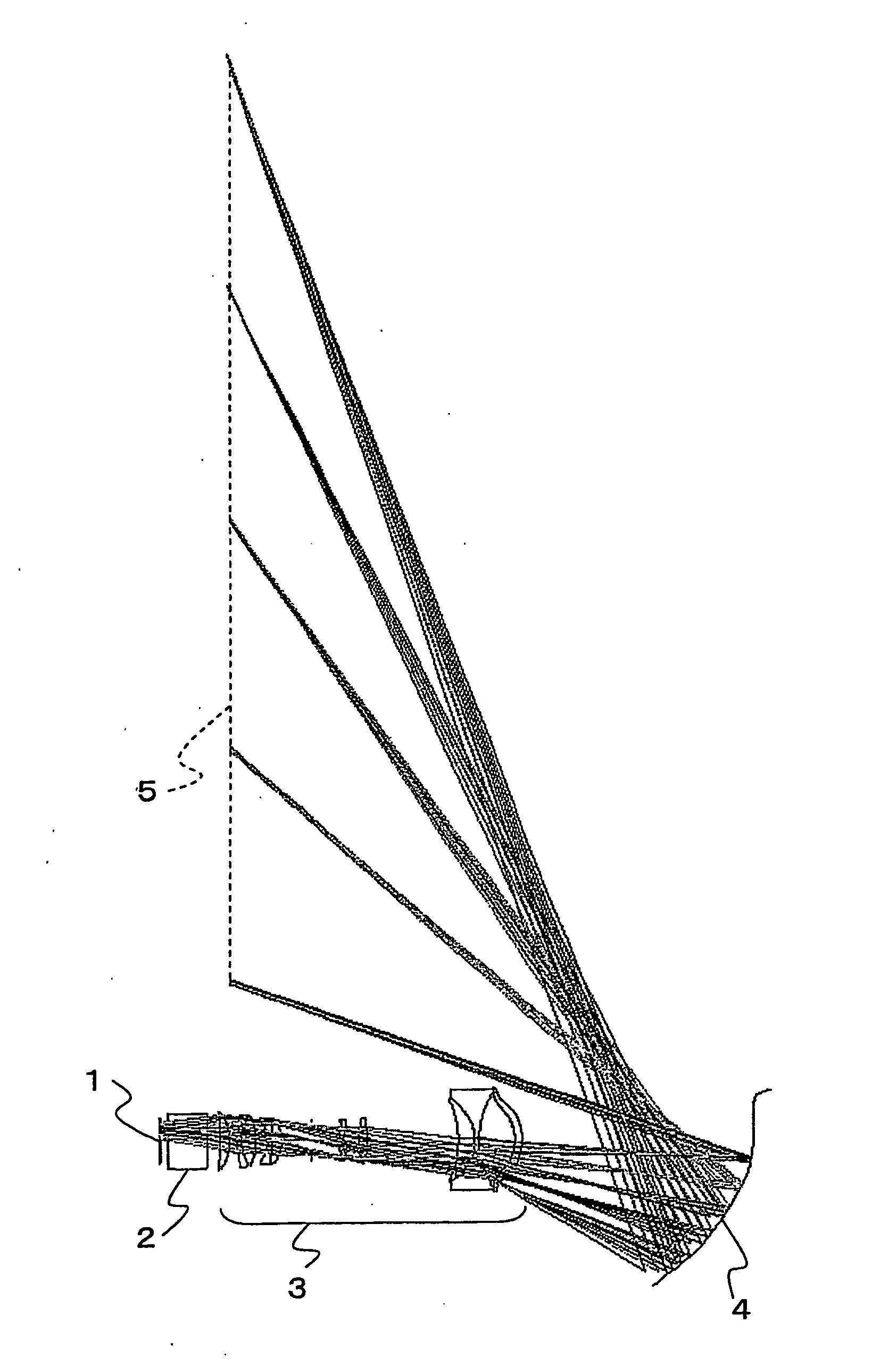
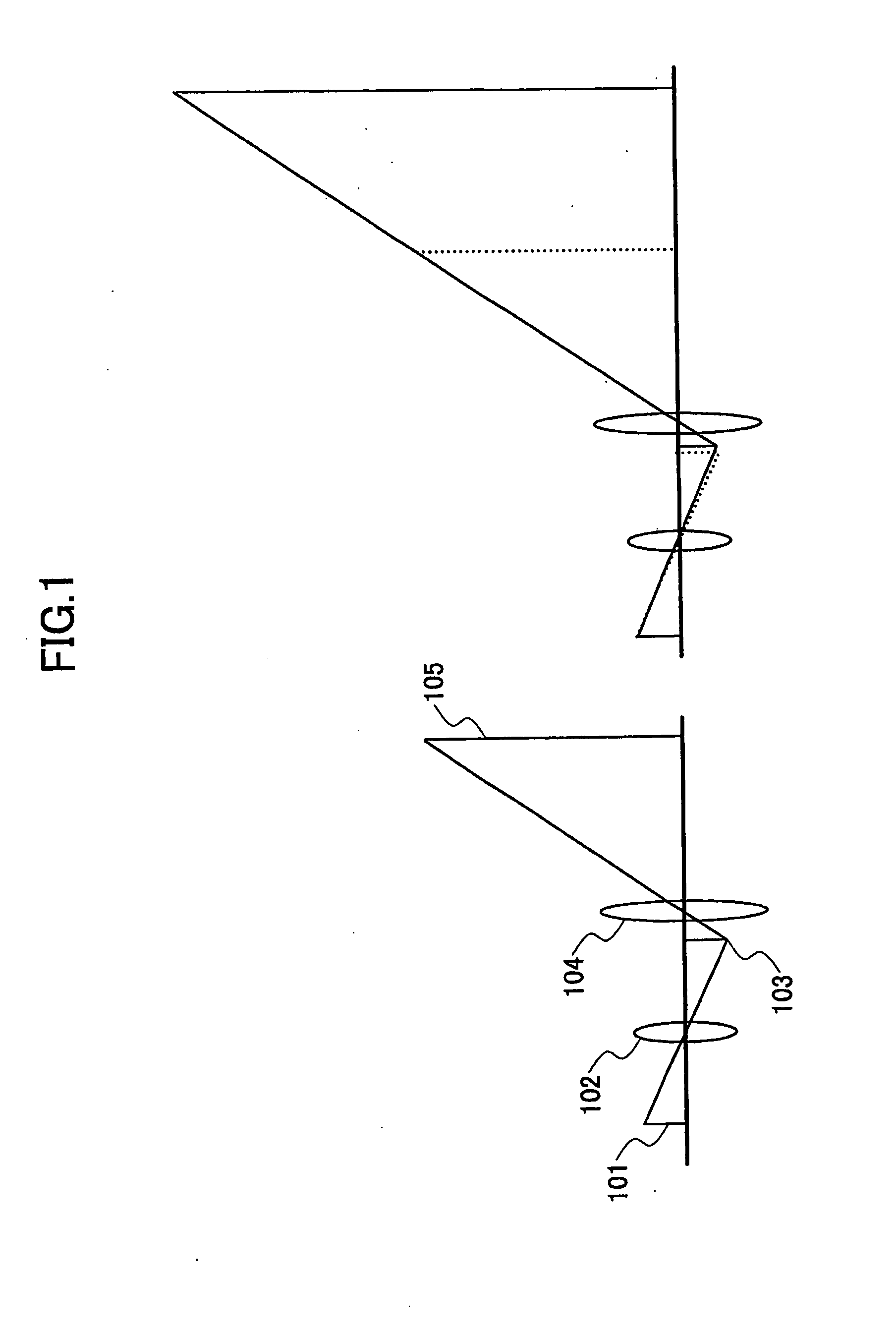
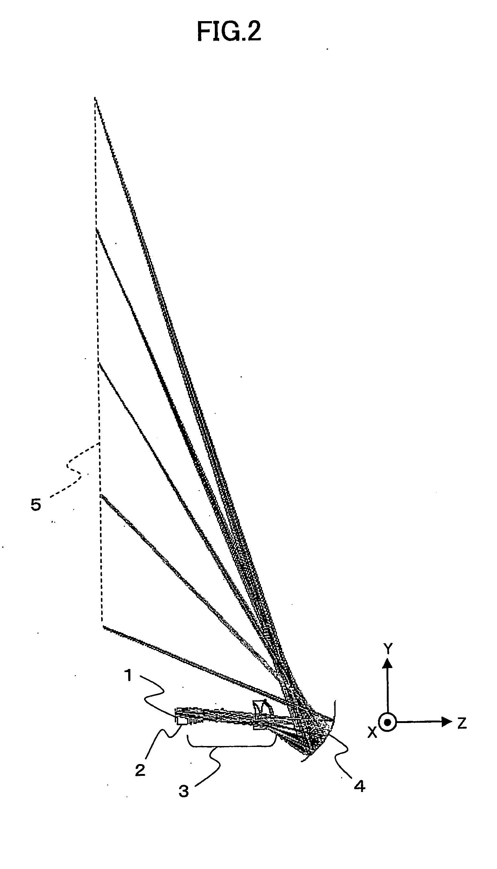
[0093]the present invention is a projection optical system including a first optical system for forming a first image conjugated with an object and a second optical system for projecting a second image conjugated with the first image toward a projection surface, in which at least one of the first optical system and second optical system includes at least one optical element(s) movable relative to the object, wherein the image distance of the projection optical system is changed and the size of the second image is changed, by moving at least one of the optical element(s) relative to the object.
[0094]Herein, the projection surface may be a component of the projection optical system or may not be a component of the projection optical system. For example, when the projection surface is a component of the projection optical system, the position of the projection surface may be brought into identical to the position of the second image by moving components including the projection surface...
second embodiment
[0194]According to the present invention, it may be possible to provide an image projecting apparatus that includes a projection optical system which includes a first optical system for forming a first image conjugated with an object and a second optical system for projecting a second image conjugated with the first image toward a projection surface wherein the image distance thereof is changed and the size of the second image is changed.
[0195]For example, the image projecting apparatus may be an image displaying apparatus having at least one image forming element, an illumination optical system for illuminating the image forming element, and a projection optical system for enlarging or reducing a light image signal modulated by the image forming element, wherein the projection optical system is any of the projection optical systems described above.
[0196]In this case, an image displaying apparatus using a novel projection optical system may be attained which is capable of enlarging ...
embodiment (
[03601) is a projection optical system comprising a first optical system configured to form a first image conjugated with an object and a second optical system configured to project a second image conjugated with the first image toward a projection surface, in which at least one of the first optical system and second optical system comprises at least one optical element(s) movable relative to the object, characterized in that an image distance of the projection optical system is changed and a size of the second image is changed, by moving at least one of the optical element(s) relative to the object.
[0361]Embodiment (2) is the projection optical system as described in embodiment (1) above, characterized in that a distance between the first image and the second optical system is changed by moving at least one of the optical element(s) relative to the object.
[0362]Embodiment (3) is the projection optical system as described in embodiment (1) or (2) above, characterized in that the fir...
PUM
 Abstract
Description
Claims
Application Information