Universal assembly tool

A jig and base technology, which is applied to manufacturing tools, workpiece clamping devices, etc., can solve the problems of inconvenient jig management and increased production costs.

Inactive Publication Date: 2007-08-15
BENQ CORP
View PDF0 Cites 29 Cited by
  • Summary
  • Abstract
  • Description
  • Claims
  • Application Information

AI Technical Summary

Problems solved by technology

[0002] Please refer to Fig. 1, the size of the existing assembly jig is designed according to the size of the assembled object. Taking the assembled LCD TV as an example, the assembly jig 1 includes a base 11 and a support 12, and the support 12 is designed On the two sides of the base 11 to support the LCD TV, in the process of assembling LCD TVs of different sizes, it is necessary to select the corresponding assembly jigs,

Method used


Image

  • Universal assembly tool
  • Universal assembly tool

Examples


Embodiment Construction

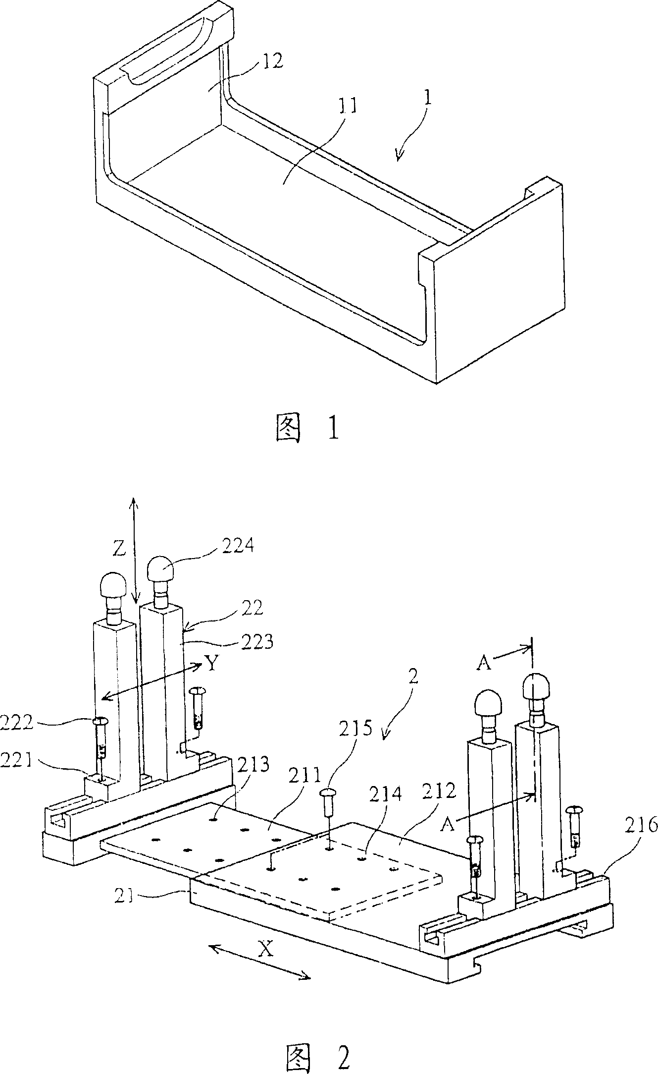
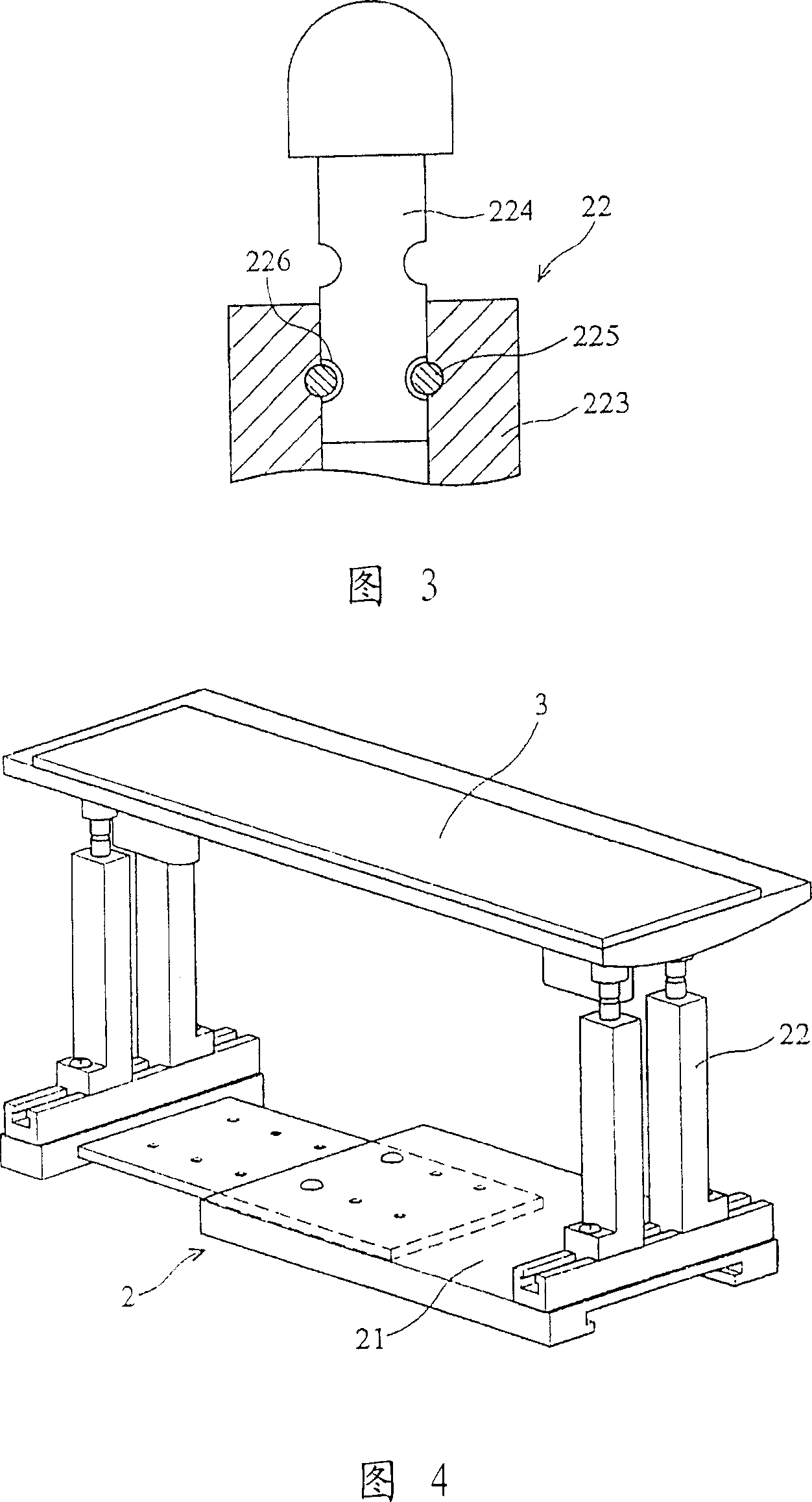
[0037] Please refer to Fig. 2, the assembly universal jig 2 includes a telescopic base 21 and a plurality of support members 22 located at the bottom. In this embodiment, two support members 22 are respectively arranged at the two ends of the telescopic base 21. When the LCD TV is assembled To provide support, the telescopic base 21 of this embodiment includes a first plate 211 and a second plate 212, the first plate 211 and the second plate 212 overlap each other and perform telescopic movements in the X-axis direction , so that the assembly universal jig 2 can obtain an appropriate length, and the first plate 211 is provided with a plurality of first positioning parts 213, and the second plate 212 is provided with a plurality of holes 214 in cooperation with the first positioning parts 213, when When the first plate 211 stretches to a proper position relative to the second plate 212, the first positioning portion 213 will overlap with the hole 214, and then a first positionin...


PUM


Abstract

The invention discloses a detachable general smelt device and a device for producing relative electric device, wherein the detachable general smelt device comprises a flexible base and several supports on the base, while the supports can move on the flexible base and the base and the supports can adjust size of the smelt device in three dimensions, and the device for producing the electric device comprises said general smelt device.

Description

technical field [0001] The invention relates to a general assembly jig, in particular to a jig used for assembling a liquid crystal television base (LCD TV base). Background technique [0002] Please refer to Fig. 1, the size of the existing assembly jig is designed according to the size of the assembled object. Taking the assembled LCD TV as an example, the assembly jig 1 includes a base 11 and a support 12, and the support 12 is designed On the two sides of the base 11 to support the LCD TV, in the process of assembling LCD TVs of different sizes, it is necessary to select the corresponding assembly jigs, that is to say, when the production line wants to change and assemble another size of LCD When using a TV, it is necessary to replace the jigs of the corresponding size at the same time. Since there are many types of LCD TVs, if you need to design the assembly jigs for each size of LCD display, it will not only cause damage to the management of the jigs Considerable inco...

Claims


Application Information

Patent Timeline
IPC IPC(8): B25B11/02
Inventor 许志宏赖裕仁沈晖庭
Owner BENQ CORP
Why Eureka
Try Eureka