Vacuum bag processing of composite parts using a conformable vacuum bag assembly

a vacuum bag and composite part technology, applied in the direction of coatings, etc., can solve the problems of reducing local, limiting the ability of air and volatiles to escape from the laminate, and material scrap, so as to reduce bagging time, labor costs and material scrap, and reduce bagging time. , the effect of loose fitting over the par

Active Publication Date: 2017-07-18
THE BOEING CO
View PDF6 Cites 1 Cited by
  • Summary
  • Abstract
  • Description
  • Claims
  • Application Information

AI Technical Summary

Benefits of technology

[0008]The disclosed embodiments provide a method of vacuum bag processing composite laminate parts which reduces bagging time, bag handling, labor costs and material scrap. The embodiments employ a vacuum bag assembly that may be quickly and easily deployed and loosely fitted over a part. Hand formation of bag pleats at precise locations on the part is substantially eliminated; instead, any bag pleats that may be needed can be formed at any convenient location on the part. The vacuum bag assembly employs a stretchable vacuum bag attached to a one-piece, stretchable breather that is substantially coextensive with the vacuum bag. The use of a one-piece breather allows all areas of the part to be covered with breather material, thus eliminating the need for cutting and hand placement of individual breather elements. When autoclave and vacuum bag pressure are applied along with heat during curing, the breather stretches and conforms to surface features of the part, such as inside radii. The ability of the breather to stretch substantially reduces or eliminates breather bridging that can result in gaps and related low pressure areas beneath the vacuum bag.

Problems solved by technology

Curing composite laminate parts and adhesives using the processes mentioned above presents a number of challenges where a part has certain geometries and / or surface contours such as inside radii.
For example, breathers may have difficulty in conforming to an inside radius on the part, resulting in what is commonly referred to as “bridging”, in which the breather and overlying vacuum bag bridge over the area of the radius.
Bridging may have the undesired effect of reducing the local compaction pressure that is applied to the part.
Alternatively, the use of breather material in contoured part areas may be completely avoided, however the absence of a breather in these areas may limit the ability of air and volatiles to escape from the laminate.
Multiple piece breathers are labor intensive to cut and install, and result in material scrap.
In some applications, the lack of a breather in areas of the part where bridging is probable may result in inadequate breathing of these areas.
Another challenge presented in vacuum bag processing of parts with certain geometries involves the placement and positioning of the vacuum bag over the breather.
The bagging process usually results in local accumulations of excess bag material in some areas of the part.
However, the need to hand form each pleat in the bag material is time consuming and labor intensive.
Moreover, the use of a bag pleat in a radiused area of the part may not reduce bridging of the breather material to the desired extent.

Method used


Image

  • Vacuum bag processing of composite parts using a conformable vacuum bag assembly
  • Vacuum bag processing of composite parts using a conformable vacuum bag assembly
  • Vacuum bag processing of composite parts using a conformable vacuum bag assembly

Examples


Embodiment Construction

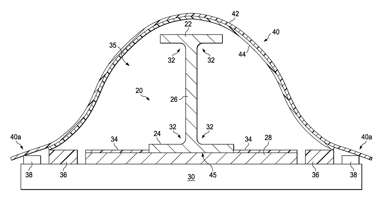
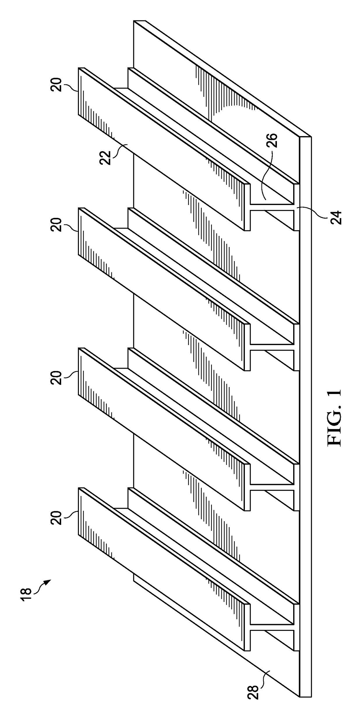
[0029]Referring to FIG. 1, the disclosed embodiments relate to vacuum bag processing of composite laminate parts, such as a composite skin 28 stiffened by composite stringers 20. The stringers 20 and the skin 28 are co-bonded using a bonding adhesive (not shown), however other joining techniques requiring vacuum bagging are possible, including those using autoclave or out-of-autoclave processes. In the illustrated embodiment, each of the stringers 20 has an “I” shaped cross-section, comprising upper and lower caps 22, 24 respectively, connected by a web 26. Other cross sectional stringer shapes are possible, including but not limited to “C”, “Z”, “L”, “J” and “hat” shapes. The stringers 20 and composite skin 28 are merely illustrative of a wide range of composite parts having one or more contours that may be processed using a vacuum bag assembly according to the embodiments described below.

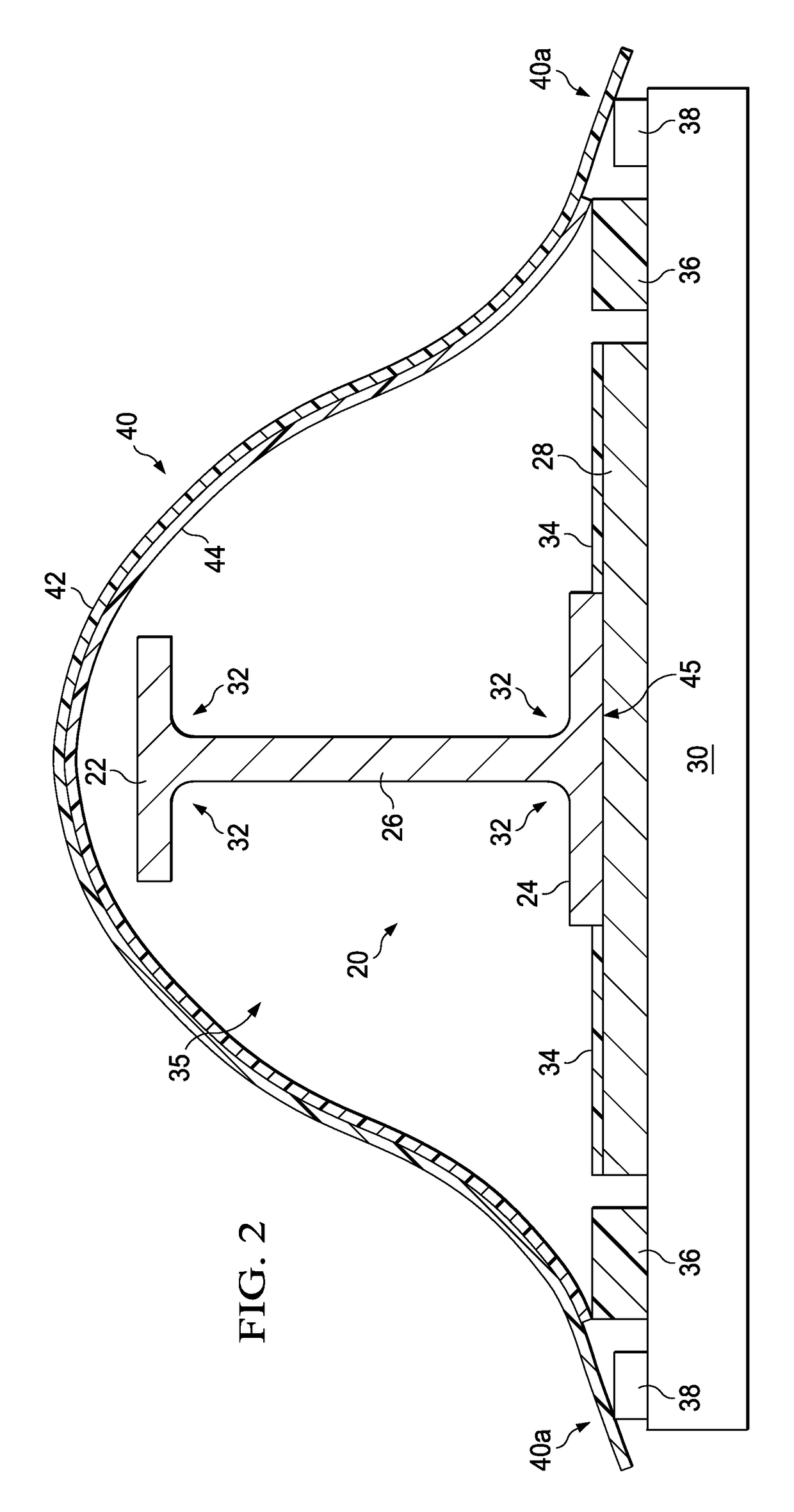
[0030]Attention is now directed to FIG. 2 which illustrates a part assembly 35 placed on a too...


PUM

PropertyMeasurementUnit
elongationaaaaaaaaaa
thicknessaaaaaaaaaa
stretchableaaaaaaaaaa

Abstract

A vacuum bag assembly is used to process the composite part. The vacuum bag assembly includes a stretchable vacuum bag attached to a stretchable breather.

Description

BACKGROUND INFORMATION[0001]1. Field[0002]The present disclosure generally relates to vacuum bag processing of composite parts, and deals more particularly with a vacuum bagging method using a stretchable vacuum bag assembly that conforms to contoured surfaces of the parts.[0003]2. Background[0004]Composite laminate parts may be cured using autoclave or out-of-autoclave processes. These processes typically employ a combination of heat and pressure applied by a vacuum bag to compact and consolidate the part. A breather may be placed between the part and the vacuum bag in order to allow escape of air and volatiles from the laminate, and thereby avoid undesired entrapment of these gases.[0005]Curing composite laminate parts and adhesives using the processes mentioned above presents a number of challenges where a part has certain geometries and / or surface contours such as inside radii. For example, breathers may have difficulty in conforming to an inside radius on the part, resulting in...

Claims


Application Information

Patent Timeline
Patent Type & Authority Patents(United States)
IPC IPC(8): B29C33/10B29C70/44B29C70/34B29C37/00B29C43/36
CPCB29C33/10B29C37/0064B29C43/3642B29C70/342B29C70/443
Inventor LOUIE, MICHAEL K.DULL, KENNETH M.AQUINO, TIMOTHY DAVIDLATHROP, PHILLIP KELLER
Owner THE BOEING CO
Why Eureka
Try Eureka