Universal case lube tray

a lubricating tray and universal technology, applied in the direction of weapons, ammunition, weapon components, etc., can solve the problems of not all cases are equally and thoroughly lubricated, dissolving and diluting gunpowder, and reducing the efficiency and effectiveness of lubricating firearm cartridges

Active Publication Date: 2017-08-08
BOYD CARL B
View PDF13 Cites 2 Cited by
  • Summary
  • Abstract
  • Description
  • Claims
  • Application Information

AI Technical Summary

Benefits of technology

[0016]It is therefore an objective of the present invention to address the above concerns and to provide a new apparatus to improve the efficiency and effectiveness of lubricating firearm cartridges and cases used in the reloading process. As such, the general purpose of the present invention is to provide a new and improved case lube tray designed to assist with the organization, positioning and lubrication of firearm cases.
[0017]Another objective of the present invention is to provide a new and improved case lube tray having a plurality of lubricating chambers and each lubricating chamber featuring a semicircle flooring and a floor center. The array of lubricating chambers will make the reloading process easier and provide quick and easy access to 50 rounds of cases after lubrication.
[0018]Another objective of the present invention is to provide a case lube tray which provides for the orientation of cases in a horizontal position. After a spray lubricant is applied, the user can rotate the cases 180 degrees with a slight hand motion and spray the lubricant a second time for an even application.
[0019]Still another objective of the present invention is to provide a novel case lube tray of simple and inexpensive construction, for use with firearm cases and having a universal molding for production into various sizes and colors to closely fit a variety of pistol or rifle cases.

Problems solved by technology

This method is time intensive and not efficient.
One is able to lubricate more cases in a shorter period of time but this method has three inherent flaws.
First, not all cases are equally and thoroughly lubricated.
Second, the interior portion of the cases become wet and contaminated with the lubricant, thereby dissolving and diluting the gunpowder.
Third, one has to wait a minimum of five minutes to allow the interior of the cases to dry prior to initiating the reloading process.
This process can become quite messy.
Finally, the cases can become disorganized and often scattered because the case lube pad has no walls or individual cylinders.
One is able to lubricate more cases in a shorter period of time but this method has three inherent flaws.
First, not all cases are equally and thoroughly lubricated.
Second, the interior portion of the cases become wet and contaminated with the lubricant; thereby dissolving and diluting the gunpowder.
Third, one has to wait a minimum of five minutes to allow the interior of the cases to dry prior to initiating the reloading process.
Compromising the dryness of the interior would cause the gunpowder to dissolve and dilute.

Method used


Image

  • Universal case lube tray
  • Universal case lube tray
  • Universal case lube tray

Examples


Embodiment Construction

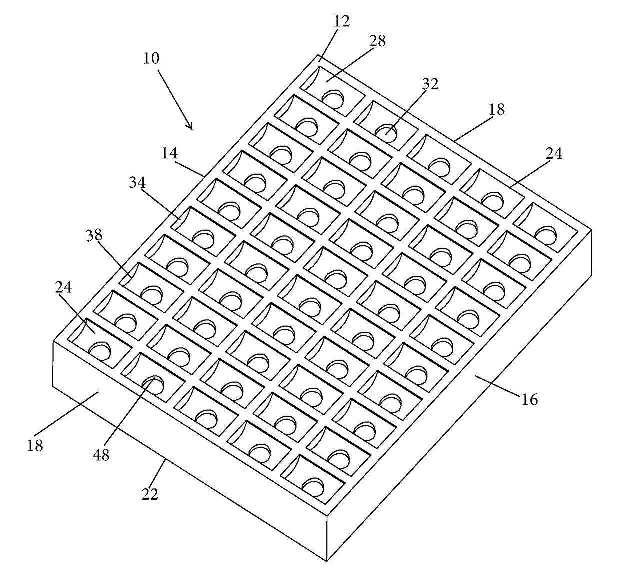
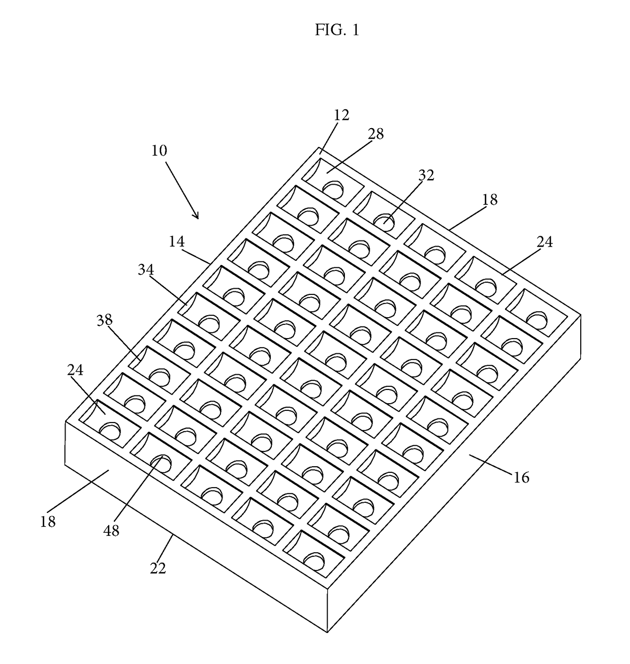
[0029]Referring now to the drawings, FIG. 1 shows the preferred embodiment of the case lube tray of the present invention generally indicated by the numeral 10. The case lube tray 10 has an exterior frame and is provided with a top frame 12, a front wall 14, a back wall 16, and side walls 18 being integral and forming a generally rectangular-shaped base 22. The top frame 12 is provided with openings defining a plurality of lubricating chambers 24.

[0030]The lubricating chambers 24 are mounting and lubricating means for shell cases 26 and are arranged in an array of horizontal rows and vertical columns. The shell cases 26 are mounted in a horizontal manner in each lubricating chamber 24 and prepared for lubrication. The user can inspect the lot and search for damaged shell cases 26, residual brass shavings from case-trimming and sort the shell cases 26 by size. The shape of each lubricating chamber 24 is such that appropriate spacing is kept between each shell case 26 and provides a c...


PUM


Abstract

A case lube tray having an integrally formed polyurethane casing is provided. The case lube tray openings define a plurality of lubricating chambers being used to lubricate shell casings in a horizontal position. The lubricating chambers are mounted on the top frame of the case and are arranged in an array of horizontal rows and vertical columns. Each lubricating chambers features semicircle flooring and a floor center. The semicircle flooring is linear and is supported by front and back lateral walls. The floor center of each lubricating chamber has centrally disposed lateral slots that further allow a user to erect and lubricate shell cases in a vertical position.

Description

BACKGROUND OF THE INVENTION[0001]The present invention relates to a case lube tray apparatus designed to assist with the organization, positioning and lubrication of firearm cartridges used in the reloading process.[0002]Reloading refers to the private manufacture of cartridges and shell cases (hereinafter cases) using previously fired cases and shotgun hulls using new bullets, shot, primers, and powder. Reloading is also the process of loading firearm cartridges or shotgun shells by assembling the required components rather than purchasing completely assembled, factory-loaded ammunition.[0003]Loading trays are a necessary part of the reloading process. The user can stay organized and continue the reloading process with smaller batches of cases. The cases can remain stationary and prevent dust and other debris from covering the reloading area. The loading trays are also helpful to prevent brass from falling over on a workbench and further causing a messy reloading process. Most load...

Claims


Application Information

Patent Timeline
Patent Type & Authority Patents(United States)
IPC IPC(8): F42B33/14F42B33/10
CPCF42B33/10F42B33/14
Inventor BOYD, CARL B.
Owner BOYD CARL B
Why Eureka
Try Eureka