Lighting device, display device, and television device

a technology for display devices and light sources, applied in the direction of instruments, optical light guides, optics, etc., can solve the problems of degrading the light use efficiency of light emitted by light sources, and achieve the effect of reducing the size of components and improving optical design

Active Publication Date: 2017-10-10
SHARP KK
View PDF7 Cites 0 Cited by
  • Summary
  • Abstract
  • Description
  • Claims
  • Application Information

AI Technical Summary

Benefits of technology

[0030]According to the technology disclosed herein, variation in size of components is reduced and an optical design is maintained preferable.

Problems solved by technology

In the edge-light type backlight device, a light guide plate may thermally expand and the expansion of the light guide plate may change the distance between a light source, such as LEDs, and the light guide plate and this may degrade light use efficiency of light emitted by the light sources.

Method used


Image

  • Lighting device, display device, and television device
  • Lighting device, display device, and television device
  • Lighting device, display device, and television device

Examples


first embodiment

[0045]A first embodiment will be described with reference to the drawings. A liquid crystal display device (an example of a display device) 10 according to this embodiment will be described. X-axis, Y-axis, and Z-axis are indicated in some drawings. The axes in each drawing correspond to the respective axes in other drawings. The Y-axis direction corresponds to a vertical direction and the X-axis direction corresponds to a horizontal direction. An upper side and a lower side are based on the vertical direction unless otherwise specified.

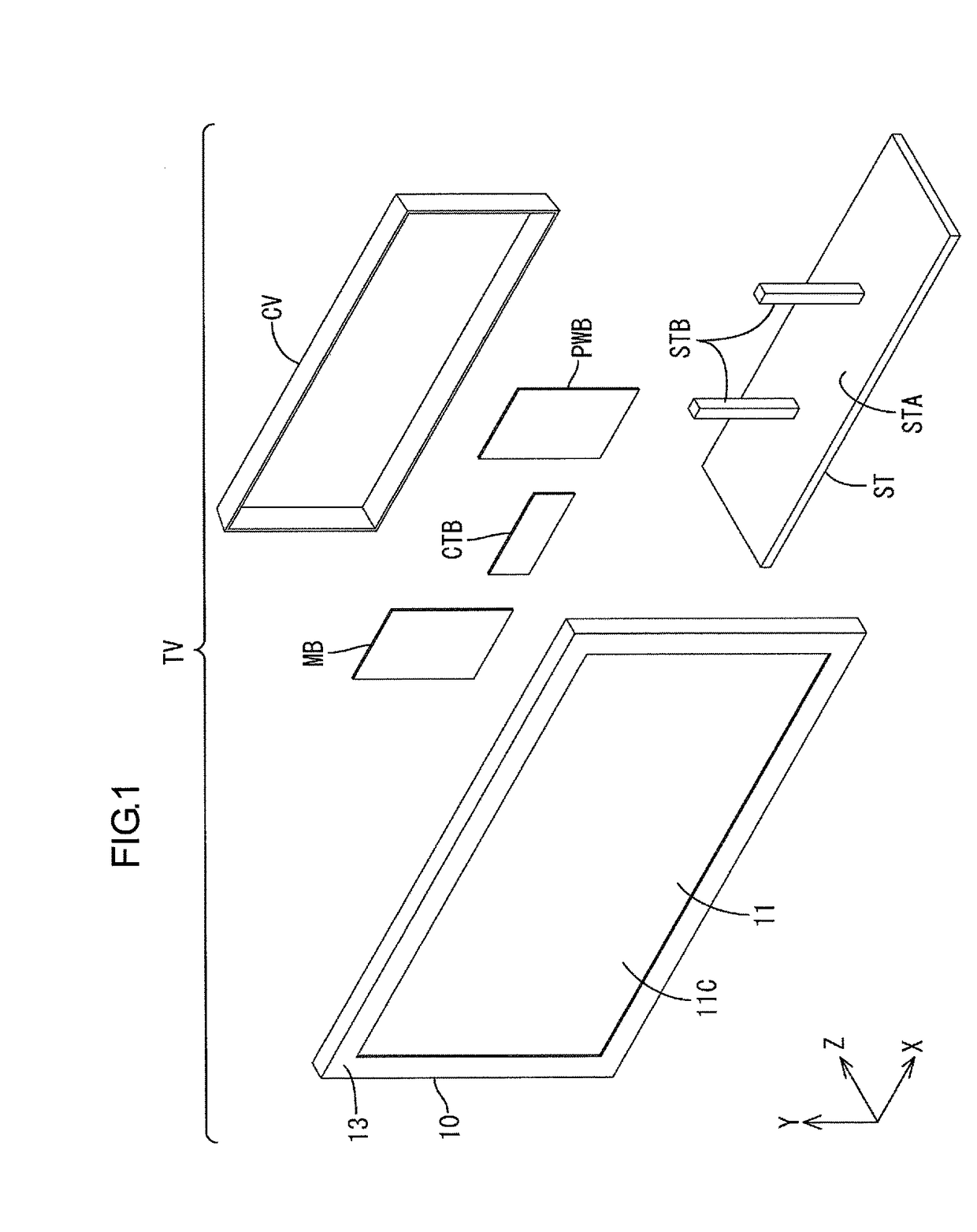
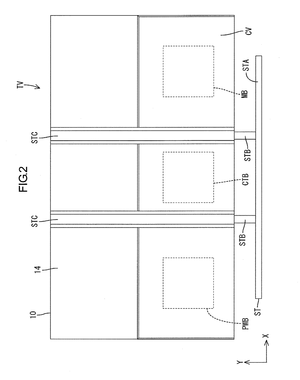
[0046]As illustrated in FIG. 1, a television device TV includes a liquid crystal display device 10, boards PWB, MB, and CTB, a cover CV, and a stand ST. The boards PWB, MB, and CTB are attached to a rear surface (a back surface) of the liquid crystal display device 10. The cover CV is attached to the rear surface of the liquid crystal display device 10 so as to cover the boards PWB, MB, and CTB. The stand ST holds the liquid crystal display device 10...

second embodiment

[0079]A second embodiment will be described with reference to drawings. According to the second embodiment, the projections 119T are different in shape from those in the first embodiment. Other configurations are same as those in the first embodiment and therefore, the constructions, functions, and effects similar to those of the first embodiment will not be described. In FIGS. 9, 10, and 11, portions represented by numerals that are equal to the numerals in FIGS. 6, 7, and 8 with 100 added thereto have the same configurations as the portions represented by the respective numerals in the first embodiment.

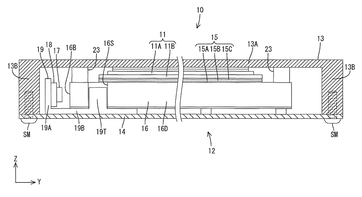
[0080]As illustrated in FIG. 9, in a backlight device 112 according to the second embodiment, a bottom plate portion 119B of the heat dissipation member 19 includes the projections 119T that project from portions thereof, that is, from end portions of a long dimension of the bottom plate portion 119B (in the X-axis direction) toward a light exit surface 116A (toward the front side),...

third embodiment

[0083]A third embodiment will be described with reference to the drawings. Projections 219T included in a heat dissipation member 219 in the third embodiment are different in shape from those in the first embodiment. Other configurations are same as those in the first embodiment and therefore, the constructions, functions, and effects similar to those of the first embodiment will not be described. In FIGS. 12 and 13, portions represented by numerals that are equal to the numerals in FIGS. 12 and 13 with 200 added thereto have the same configurations as the portions represented by the respective numerals in the first embodiment.

[0084]As illustrated in FIGS. 12 and 13, in a backlight device 212 according to the third embodiment, the projections 219T project from two ends of a longitudinal dimension of a bottom plate portion 219B (the X-axis direction) toward the front and continue to an upstanding portion 219A. In other words, the projections 219T are at two ends of a longitudinal dim...


PUM


Abstract

A backlight device includes LEDs, a light guide plate, and a heat dissipation member. The light guide plate includes edge surfaces including a light entrance surface through which light from the LEDs enters, a front plate surface as a light exit surface through which the light from the LEDs exits, and another plate surface as an opposed surface on an opposite side from the light exit surface. The heat dissipation member having heat dissipating properties includes a bottom plate portion extending along the opposed surface on an opposed surface side, and an upstanding portion extending from the bottom plate portion toward the light exit surface. The bottom plate portion includes projections projecting toward the light exit surface and facing short-side edge surfaces of the light guide plate. The projections are stopped at the corresponding edge surfaces to restrict a distance between the LEDs and the light entrance surface.

Description

TECHNICAL FIELD[0001]The present invention relates to a lighting device, a display device, and a television device.BACKGROUND ART[0002]In liquid crystal display devices such as liquid crystal television devices, liquid crystal panels that are display panels do not emit light. Therefore, liquid crystal display devices require backlight devices as external lighting devices. The backlight devices are classified broadly into a direct type and an edge-light type based on mechanisms. For further reduction in thicknesses of the liquid crystal display devices, the edge-light type backlight devices are more preferable.[0003]In the edge-light type backlight device, a light guide plate may thermally expand and the expansion of the light guide plate may change the distance between a light source, such as LEDs, and the light guide plate and this may degrade light use efficiency of light emitted by the light sources. It has been known that fixing members that fix a board including the light sourc...

Claims


Application Information

Patent Timeline
Patent Type & Authority Patents(United States)
IPC IPC(8): F21V8/00
CPCG02B6/0085G02B6/0091G02B6/0088
Inventor GOTOU, AKIRA
Owner SHARP KK
Why Eureka
Try Eureka