
Fitting structure of connector

a technology of fitting structure and connector, which is applied in the direction of coupling base/case, coupling device connection, electrical apparatus, etc., can solve the problems of part of packing and inability to secure sealability, and achieve the effect of suppressing deterioration of connector sealability and shaky fitting of a housing

Active Publication Date: 2018-05-22
YAZAKI CORP +1
View PDF26 Cites 6 Cited by
  • Summary
  • Abstract
  • Description
  • Claims
  • Application Information

AI Technical Summary

Benefits of technology

[0017]According to one or more embodiments, it is possible to suppress shaky fitting of a housing and to suppress deterioration of the sealability of the connector.

Problems solved by technology

However, when the male housing is inserted into the female housing in shaky fitting, there is a concern that the male housing will be locked in a state of shifting from a normal position, as a result, part of the packing will be intensely pressed and crushed, and then it is not possible to secure sealability.

Method used


Image

  • Fitting structure of connector
  • Fitting structure of connector
  • Fitting structure of connector

Examples


Embodiment Construction

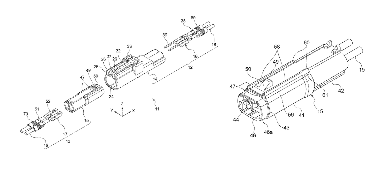
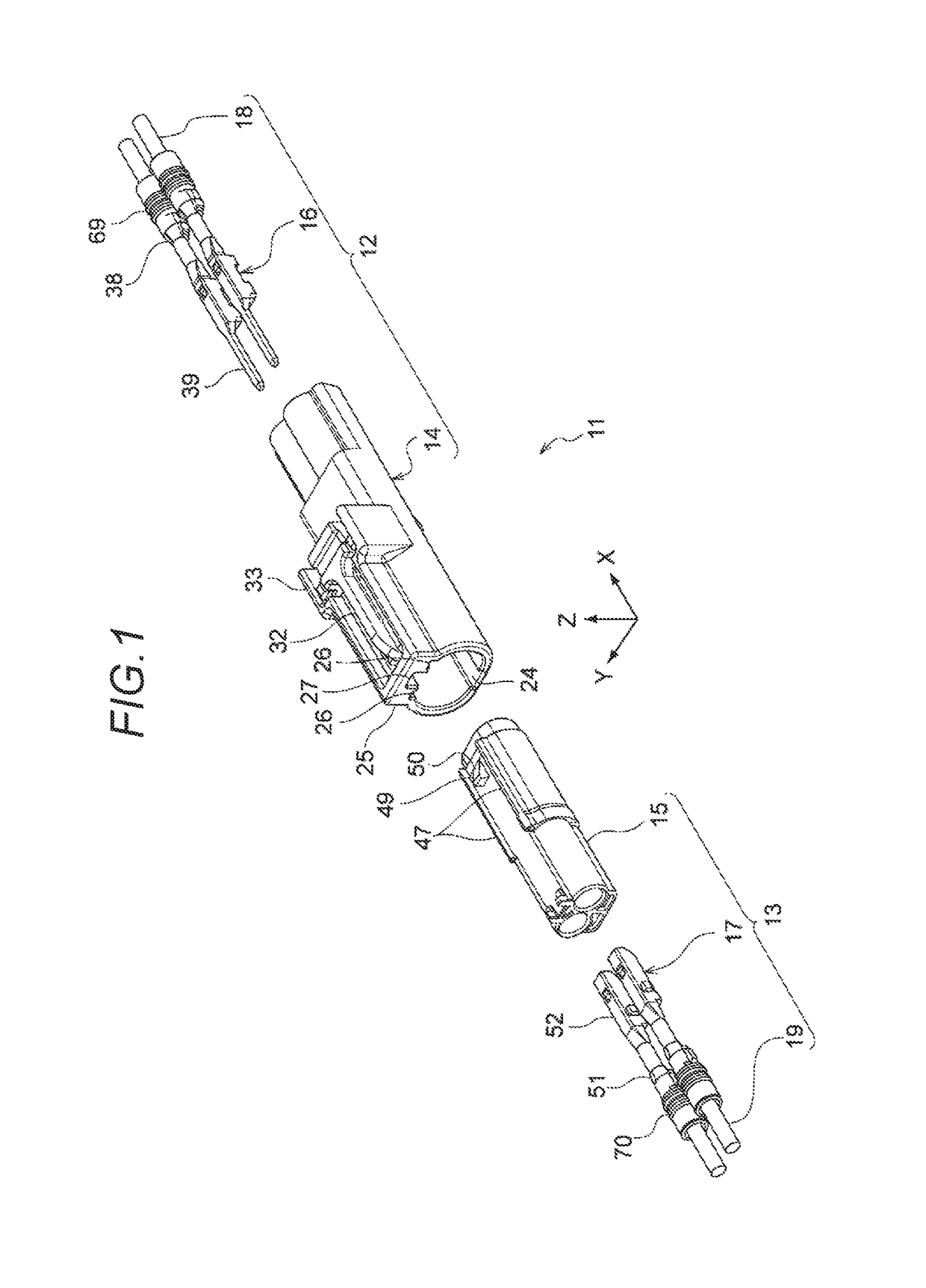
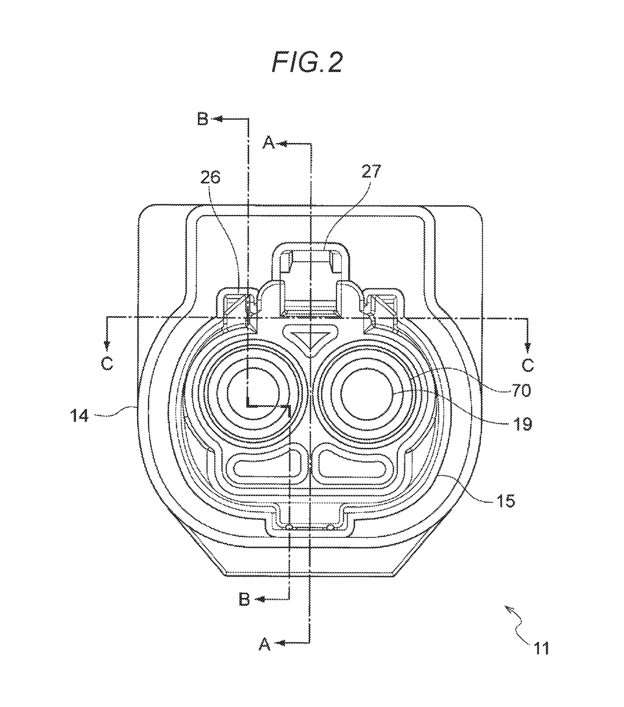
[0031]Hereinafter, one embodiment of a fitting structure of a connector, to which the present invention is applied, will be described with reference to FIG. 1 to FIG. 13. In the present embodiment, an example of a waterproof type of connector which is mounted in an automobile or the like is described; however, the connector of the present invention can be applied to a connector for another purpose.

[0032]A connector 11 of the present embodiment is configured to include a male connector 12 and a female connector 13 as illustrated in FIG. 1 and FIG. 2, in which a male housing 14 of the male connector 12 and a female housing 15 of the female connector 13 fit to each other, and a male terminal 16 accommodated in the male housing 14 is electrically connected with a female terminal 17 accommodated in the female housing 15. An electric wire 18 is connected with the male terminal 16 and an electric wire 19 is connected with the female terminal 17. The female housing 15 fits and is locked int...


PUM


Abstract

A fitting structure of a connector which fits a pair of housings to each other, the fitting structure is provided with a first step portion and a second step portion on at least a part of an outer circumferential surface of one housing, and a third step portion and a fourth step portion on at least a part or an inner circumferential surface of the other housing. The first step portion extends in an axial direction. The second step portion protrudes more highly than the first step portion and is positioned on a rear side of the first step portion and extends in the axial direction. The third step portion is in contact with the first step portion and extends in the axial direction. The fourth step portion is in contact with the second step portion and extends in the axial direction.

Description

CROSS REFERENCE TO RELATED APPLICATIONS[0001]This application claims priority from Japanese Patent Application No. 2015-34864 filed on Feb. 25, 2015, the entire contents of which are incorporated herein by reference.TECHNICAL FIELD[0002]The present invention relates to a fitting structure of a connector.BACKGROUND ART[0003]In the related art, a waterproof connector that connects wires is mounted in an automobile or the like. For example, there has been known a connector that includes a female connector having a cylindrical inner housing in which a cavity that is able to accommodate a female terminal is formed and a cylindrical outer housing that surrounds the inner housing, and a male connector having a cylindrical male housing in which a cavity that is able to accommodate a male terminal is formed, the connector is formed by fitting both connectors together.[0004]This type of connecter has an annular rubber packing mounted on an outer circumferential surface of the inner housing of...

Claims


Application Information

Patent Timeline
Patent Type & Authority Patents(United States)
IPC IPC(8): H01R13/629H01R13/52H01R13/627
CPCH01R13/629H01R13/5221H01R13/6272
Inventor HAMADA, KEIJIMIYAKAWA, TOMOYUKIOCHIAI, KAZUYUKI
Owner YAZAKI CORP
Learn More