
Branch pipe intersecting line laying out instrument
A technology of intersecting lines and pay-off instruments, which is applied to workshop equipment, manufacturing tools, etc., can solve problems such as the same or similar literature reports that have not been found, and achieve the effects of improving line drawing efficiency, high line drawing accuracy, and convenient adjustment
- Summary
- Abstract
- Description
- Claims
- Application Information
AI Technical Summary
Problems solved by technology
Method used
Image

Examples
Embodiment Construction
[0014] The embodiments of the present invention are described in detail below in conjunction with the accompanying drawings: this embodiment is implemented on the premise of the technical solution of the present invention, and detailed implementation methods and specific operating procedures are provided, but the protection scope of the present invention is not limited to the following the described embodiment.
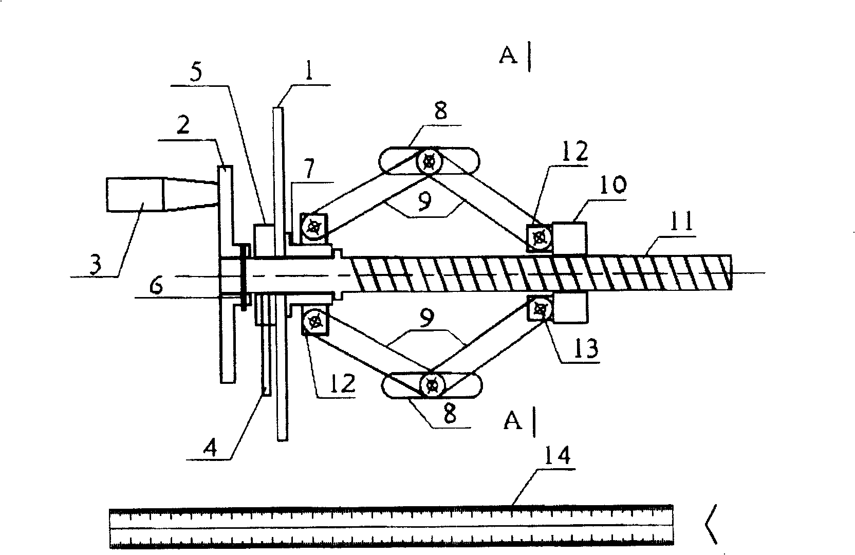
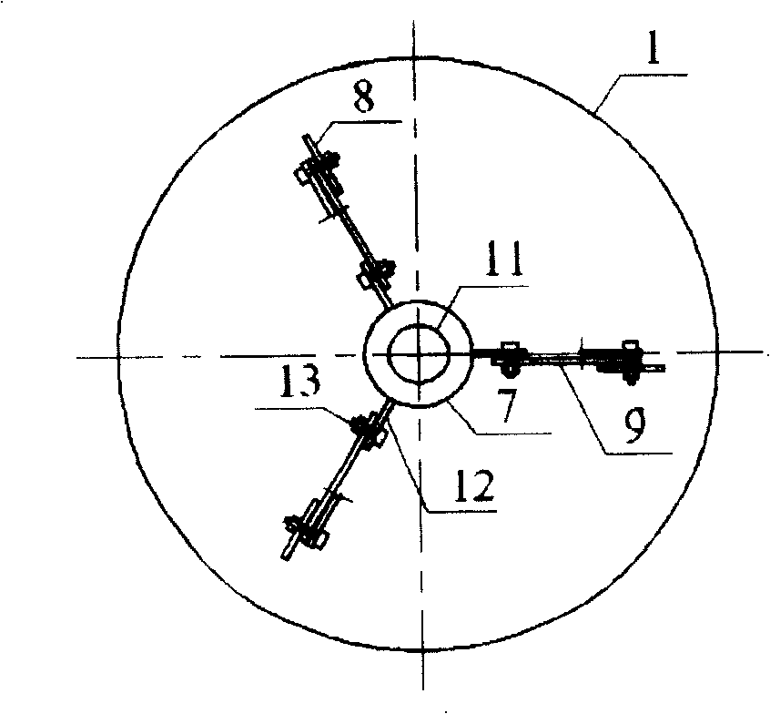
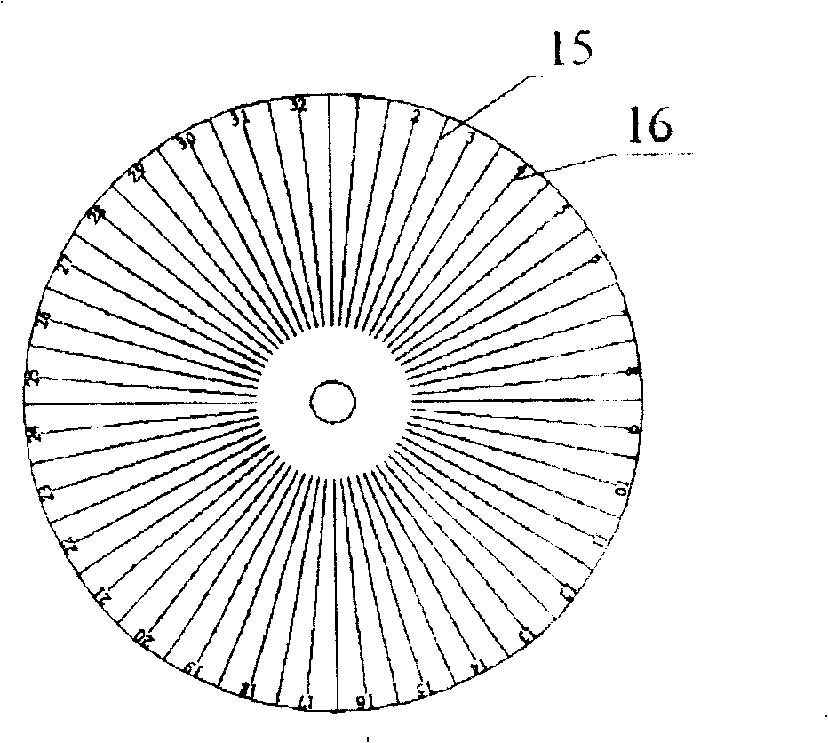
[0015] Such as Figure 1-3 As shown, the present embodiment consists of a dial 1, a rotating disk 2, a rotating handle 3, a fastening bolt 4, a fixed block 5, a fixed bolt 6, a fixed nut 7, three positioning steel sheets 8, three sets of connecting rods 9, and Moving nut 10, central shaft 11 and steel ruler 14 form. The dial 1 is connected with the fixed block 5 and the fixed nut 7, the central shaft 11 is inserted into the central hole of the dial 1, the fixed block 5 and the fixed nut 7, and then the central shaft 11 is inserted into the rotating disc 2, and the ro...
PUM
 Abstract
Description
Claims
Application Information