Overvoltage protector consitituted by multi-spark angle

A protection device and spark angle technology, applied in the direction of emergency protection circuit devices, emergency protection circuit devices, circuit devices, etc. for limiting overcurrent/overvoltage, can solve the problem of low research level of overvoltage protection devices and the ability to pass current Limitation and other issues, to achieve the effect of large export of transient pulse current and transient overvoltage, and expansion of current capacity

Inactive Publication Date: 2008-12-10
XI AN JIAOTONG UNIV
View PDF4 Cites 0 Cited by
  • Summary
  • Abstract
  • Description
  • Claims
  • Application Information

AI Technical Summary

Problems solved by technology

Since the gap-type overvoltage protection device is only composed of a pair of spark gaps, the ability to pass current is still limited to a certain extent.
However, the research work on overvoltage protection devices used in power systems in my country started relatively late, especially the research level of overvoltage protection devices with large current capacity is relatively low.

Method used


Image

  • Overvoltage protector consitituted by multi-spark angle
  • Overvoltage protector consitituted by multi-spark angle
  • Overvoltage protector consitituted by multi-spark angle

Examples


Embodiment 1

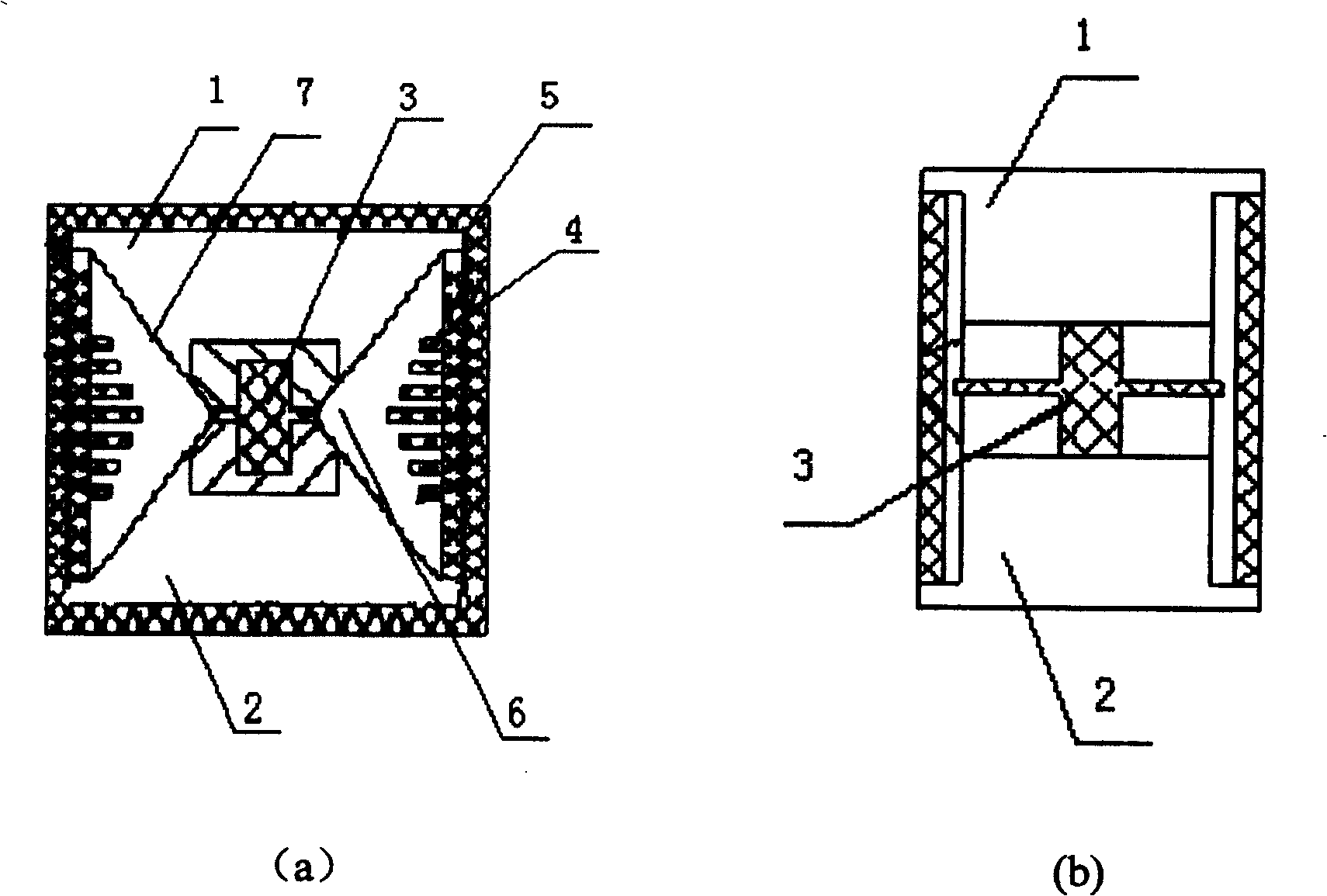
[0014] Embodiment 1: see figure 1 , the present invention comprises the electrode 1 and the electrode 2 of the frustum structure arranged in the insulating airtight casing 5 that is made of alumina ceramics, the edge of the electrode 1 and the electrode 2 of the frustum structure is set as a chamfered structure, the electrode 1 and the electrode 2 constitutes a pair of symmetrical V-shaped spark gaps 6, and an auxiliary ignition device 3 made of insulating material is also provided between the electrodes 1 and 2. The thickness of the auxiliary ignition device 3 is less than 1 mm, and the V-shaped symmetrical spark The surface of the gap 6 is the same size as the electrodes 1 and 2, and the plane perpendicular to the spark gap 6 is larger than the plane of the electrodes 1 and 2. Between the V-shaped spark gaps 6, there are also V-shaped spark gaps 6, respectively. The arc chute 4 is made of corresponding convex and concave metal or ceramic material.

[0015] In this embodimen...

Embodiment 2

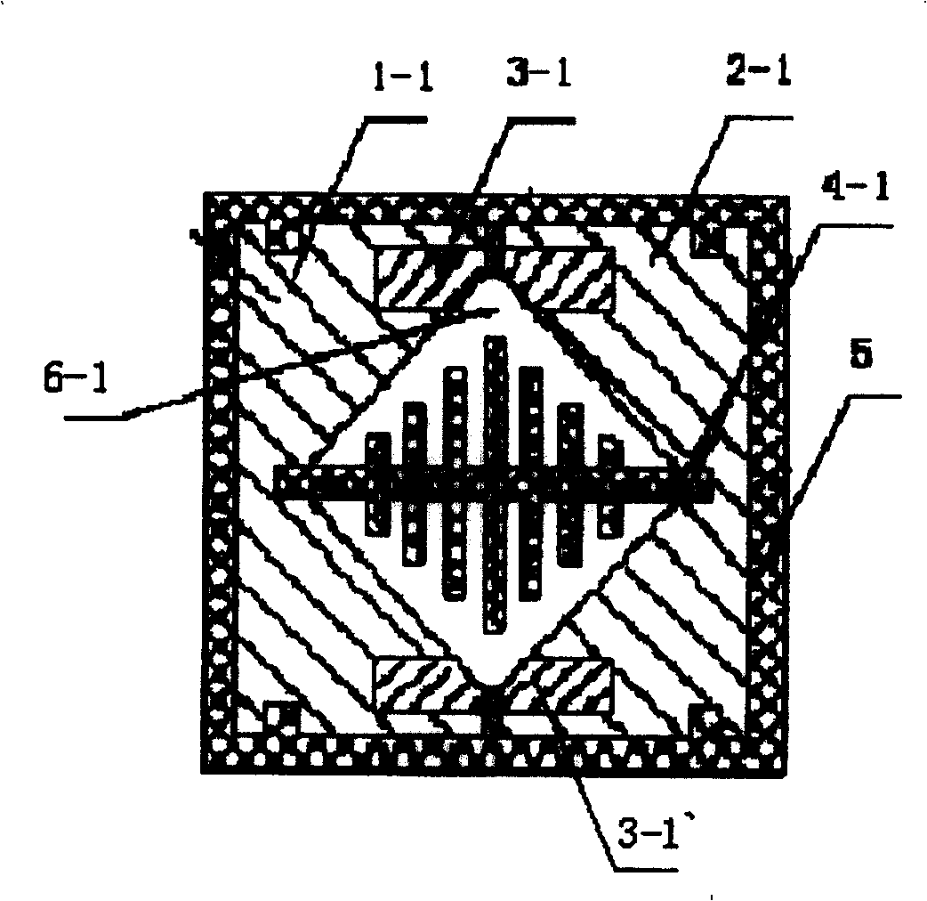
[0016] Example 2: see figure 2 , the present invention comprises the electrode 1-1 and the electrode 2-1 of " V " shape structure that are symmetrically arranged in the insulated airtight shell 5 that is made of alumina ceramics, and the electrode 1-1 and the electrode 2-1 together form two An inward "V"-shaped spark gap 6-1, and an auxiliary ignition device 3-1 made of insulating material with creeping discharge and a thickness of less than 1 mm is respectively provided on the mating surfaces of the electrode 1-1 and the electrode 2-1 1 and 3-1`, between the "V"-shaped spark gap 6-1, there is also an arc extinguishing grid 4- made of metal or ceramic material corresponding to the "V"-shaped spark gap 6-1. 1.

[0017] In this embodiment, the shape of the two electrodes 1-1, 2-1 is designed as a "V" shape structure, and the two electrodes 1-1, 2-1 are placed opposite to each other to form two face-to-face spark gaps 6-1. An auxiliary ignition device 3-1 made of insulating ma...


PUM


Abstract

An overvoltage protection device composed of a plurality of spark horns, including electrodes arranged in an insulating and airtight casing, the two electrodes are symmetrically arranged in a truss structure and an auxiliary ignition device made of insulating material is arranged between the electrodes, The electrodes with two truss structures form a pair of symmetrical V-shaped spark gaps, and arc extinguishing grids corresponding to the V-shaped spark gaps are respectively provided with alternating convex and concave arcs. In the present invention, two symmetrical frustum electrodes form two spark gaps. When the gap breaks down, the arcs on the two pairs of spark gaps move outwards under the action of electromagnetic force at the same time. Compared with the single spark gap structure, the instantaneous The state pulse current capacity is doubled. When the arc enters the arc extinguishing grid, the arc is divided into multiple arcs through the cooling of the arc, which increases the arc voltage and achieves the purpose of arc extinguishing.

Description

technical field [0001] The invention relates to an overvoltage protection device, in particular to an overvoltage protection device composed of a plurality of spark horns. Background technique [0002] In recent years, with the rapid development of the information industry, people have paid great attention to the hazards caused by atmospheric overvoltage and operating overvoltage in the system. There have been many reports on spark switches with various electrode shapes as overvoltage protection devices. Among them, the representative one is the gap type overvoltage protection device of German Phoenix Contact Co., Ltd. The device consists of two electrodes to form a "V"-shaped spark gap. When the gap is ignited, an arc is generated between the two electrodes. Under the action of electromagnetic force and heat, the arc moves forward along the V-shaped spark gap. The advantage is that it can withstand a large impact current, but the disadvantage is that the operating voltage...

Claims


Application Information

Patent Timeline
Patent Type & Authority Patents(China)
IPC IPC(8): H02H9/06H01H1/06H01H9/30
Inventor 姚学玲陈景亮刘东社孙伟
Owner XI AN JIAOTONG UNIV
Why Eureka
Try Eureka