Unlock instant, AI-driven research and patent intelligence for your innovation.

Combination type blade wheel

A combination and impeller technology, applied in non-variable pumps, components of pumping devices for elastic fluids, machines/engines, etc., can solve problems such as flow field disorder and wind pressure difference

Inactive Publication Date: 2009-07-29
杨圣安
View PDF5 Cites 0 Cited by
  • Summary
  • Abstract
  • Description
  • Claims
  • Application Information

AI Technical Summary

Problems solved by technology

[0002] Existing impeller 4, refer to Image 6 As shown, the described seed impeller 4 has a hollow casing 41. A shaft 44 is arranged in the center of the casing 41, and the periphery of the casing 41 is coaxial with the shaft 44. A plurality of blades 42 are arranged around the periphery of the casing 41, and an air guide groove 45 is formed between the blades 42 and the blades 42. Accordingly, when the existing impeller 4 rotates, the air will be guided into the air by the front edge of the blade 42. The air guide groove 45 is blown out to the trailing edge, but the air guide groove 45 of this axial flow impeller 4 is equal in width so the outlet area 450 is wider. Figure 7 As shown in the radiating blades of China New Patent Certificate No. ZL200320102753.0, although the outlet end of the air guide groove 45 is provided with booster blades 47, which can reduce the width of the outlet area 450, but because the blades 42 of the impeller 4 are arranged radially, so its air guide The outlet area 450 of the groove 45 will gradually widen toward the tail end of the blade 42, so the outlet area 450 at the tail end of the blade 42 is also wider, so it is easy to happen that the air blown out by the blade 42 rebounds back to the air guide groove, and the wind pressure is also poor and the flow field Disadvantages of mess

Method used


Image

  • Combination type blade wheel
  • Combination type blade wheel
  • Combination type blade wheel

Examples


Embodiment Construction

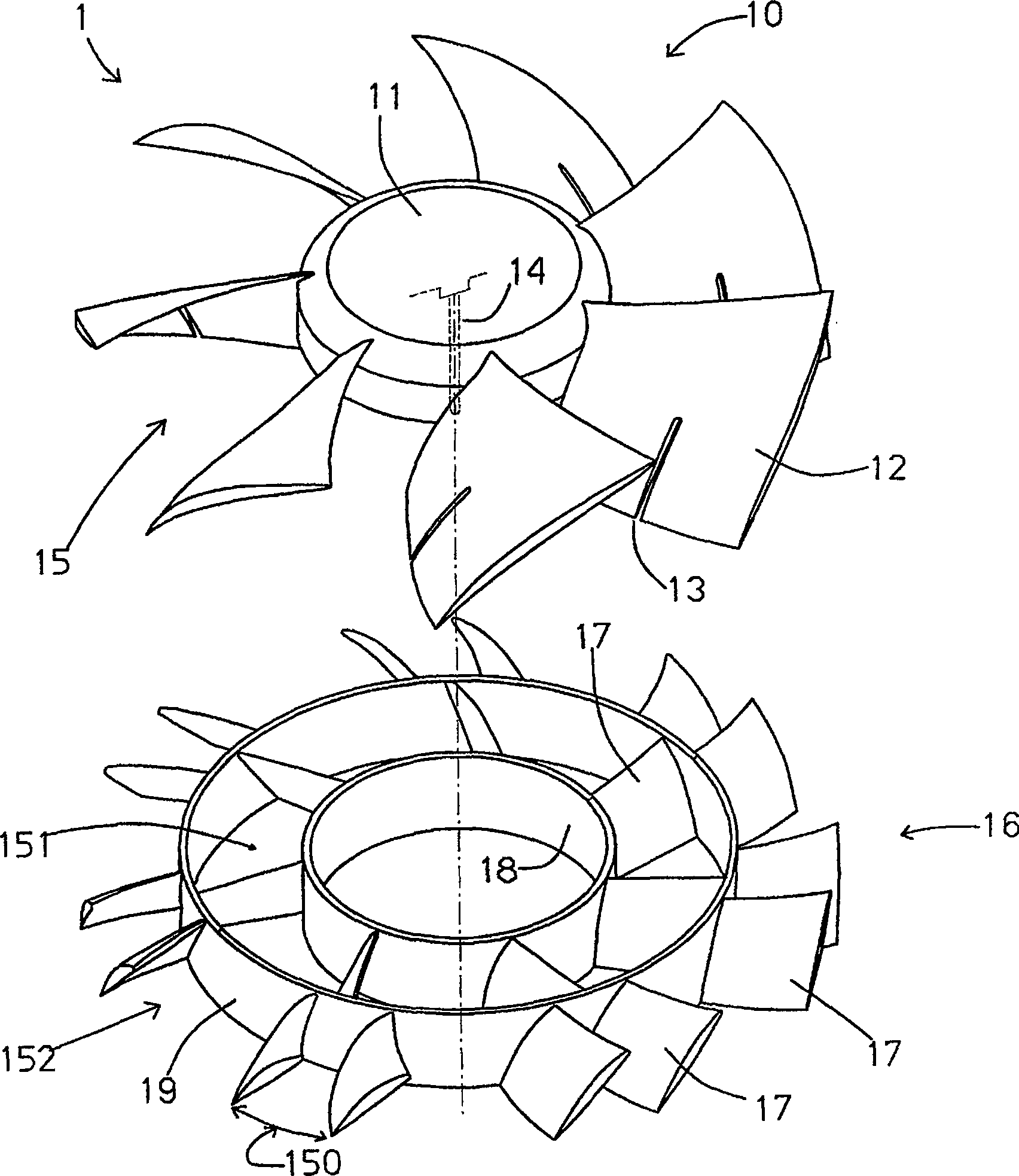
[0018] Please refer to figure 1 , figure 2 As shown, it is the structure of the first embodiment of the present invention, and the combined impeller 1 includes:

[0019] A main blade 10 has a casing 11, several blades 12 and a shaft 14, wherein a shaft 14 is arranged at the center of the top surface of the hollow casing 11, and the periphery of the casing 11 is connected to the shaft 14 For coaxial arrangement, several blades 12 are arranged around the outer periphery of the housing 11, and an air guide groove 15 is formed between the blades 12 and the blades 12, and the rear edge of the several blades 12 is provided with a gap 13;

[0020] A ring body group 16 has a housing 18, a ring body 19 and several supercharging blades 17, wherein the hollow housing 18 and the hollow ring body 19 are arranged at intervals and coaxially arranged with the main blade shaft rod 14, the described The cross-sectional shape of the casing 18 and the ring body 19 can be a rectangle with equa...


PUM


Abstract

The invention is a combined impeller, which is composed of a shell, several blades, a ring body and a shaft. A shaft is set in the center of the shell, and several pieces are set on the outer peripheral ring of the shell. The blades are coaxial with the shaft, and an air guide groove is formed between the blades. The ring body is arranged at the air outlet end of the air guide groove and is coaxial with the shaft rod. The ring body area Separated from the air guide grooves, they are respectively inner air guide grooves and outer air guide grooves, the ring body can smooth the flow field, and inner and outer booster vanes can be set in each inner and outer air guide grooves to The outlet area is reduced to increase the wind pressure and prevent the blown air from bouncing back to the air guide groove, and it is made in combination to overcome the interference of components and is not easy to demould.

Description

technical field [0001] The invention relates to an axial flow impeller structure. Background technique [0002] Existing impeller 4, refer to Image 6 As shown, the described seed impeller 4 has a hollow casing 41. A shaft 44 is arranged in the center of the casing 41, and the periphery of the casing 41 is coaxial with the shaft 44. A plurality of blades 42 are arranged around the periphery of the casing 41, and an air guide groove 45 is formed between the blades 42 and the blades 42. Accordingly, when the existing impeller 4 rotates, the air will be guided into the air by the front edge of the blade 42. The air guide groove 45 is blown out to the trailing edge, but the air guide groove 45 of this axial flow impeller 4 is equal in width so the outlet area 450 is wider. Figure 7 As shown in the radiating blades of China New Patent Certificate No. ZL200320102753.0, although the outlet end of the air guide groove 45 is provided with booster blades 47, which can reduce the wid...

Claims


Application Information

Patent Timeline
Patent Type & Authority Patents(China)
IPC IPC(8): F04D29/38
Inventor 杨圣安
Owner 杨圣安