

Digital phase detector
- Summary
- Abstract
- Description
- Claims
- Application Information
AI Technical Summary
Problems solved by technology
Method used
Image

Examples
Embodiment Construction
[0034] In order to make the object, technical solution and advantages of the present invention clearer, the present invention will be further described in detail below in conjunction with the accompanying drawings.
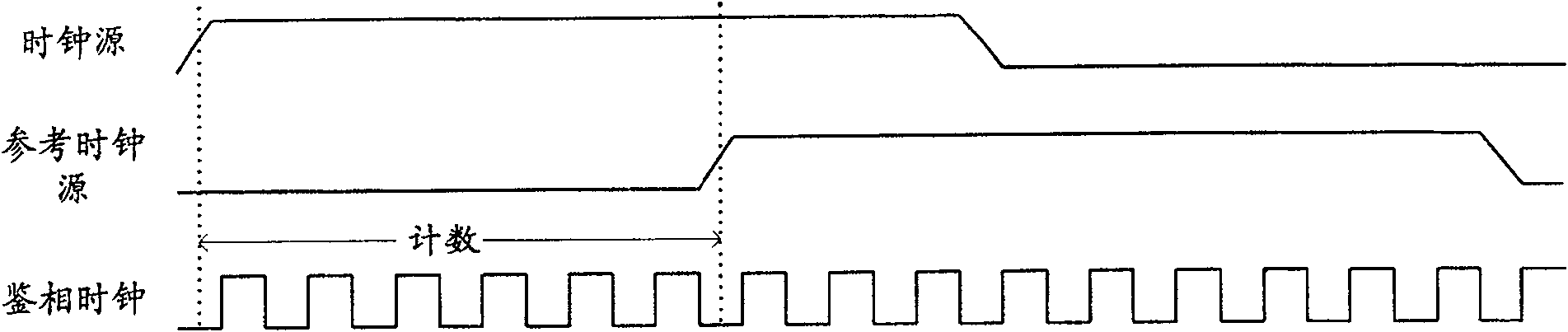
[0035] The present invention obtains several groups of phase-difference clock signals with equal phase difference by phase-shifting the phase-detection clock signal after frequency multiplication, and uses each group of phase-detection clock signals to perform phase difference counting to obtain a number of phase difference count values, and then these Synthesized to achieve higher phase detection accuracy.
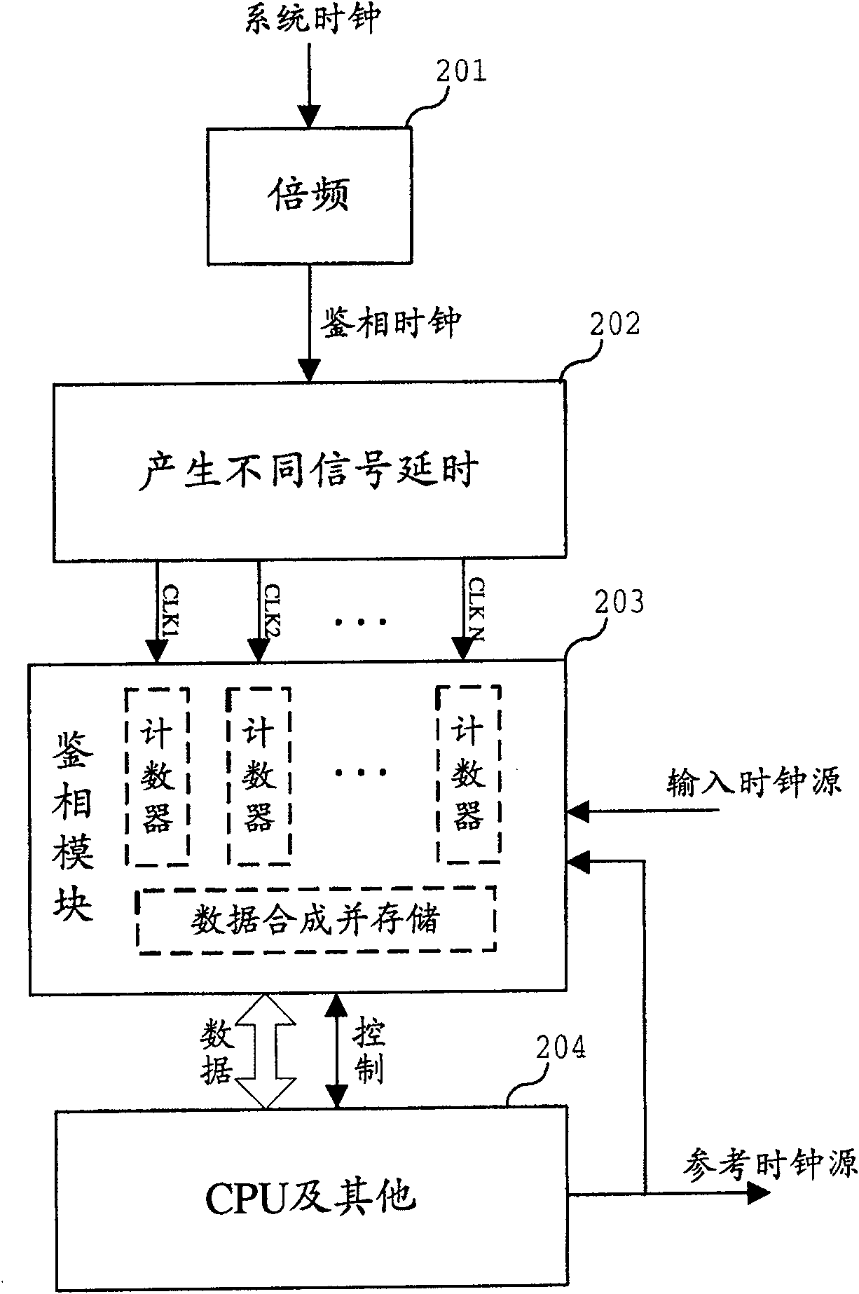
[0036] figure 2 A structural diagram of a phase detector system according to an embodiment of the present invention is shown.
[0037] First pass the system clock through the frequency multiplication module 201 to generate a high-frequency phase detection clock signal; then through the delay module 202 to generate phase detection clocks CLK1, CLK2 ... CLK N...
PUM
 Abstract
Description
Claims
Application Information