Emergency lighting device

A technology for emergency lighting and equipment, applied in the field of emergency lighting systems, can solve problems such as labor and other problems, and achieve the effects of increasing maintenance burden, reducing power consumption, and low leakage current

Active Publication Date: 2009-12-30
SIGNIFY HLDG BV
View PDF6 Cites 0 Cited by
  • Summary
  • Abstract
  • Description
  • Claims
  • Application Information

AI Technical Summary

Problems solved by technology

The disadvantage of this testing process is that it usually requires taking out of use the facility such as a tunnel, building etc. duration of lighting

Method used


Image

  • Emergency lighting device
  • Emergency lighting device

Examples


Embodiment Construction

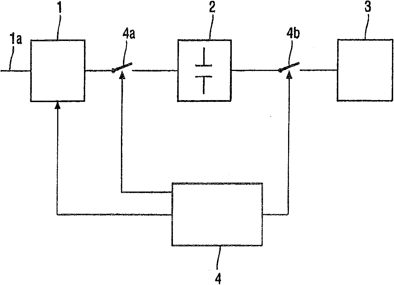
[0016] figure 1 An emergency lighting system is shown, which includes a charger 1 for charging an energy storage device, in this case a supercapacitor 2 . The charging device or charging device 1 can charge the supercapacitor 2 when a connection has been established via the switch 4a. The charging device 1 is supplied with electrical energy by means of a power source 1a, for example an electrical power source. Via the second switch 4b the energy storage device 2 can be connected to the lamp 3 for operating the lamp 3 . The lamp 3 may comprise any suitable type of lamp, such as a high or low pressure discharge lamp, a halogen lamp, a glow bulb, a luminous tube, a fluorescent lamp, a semiconductor light emitting device or any other suitable lighting device. The emergency lighting system also includes a control device 4 for controlling the charging of the charger 1 and for switching on the lamp 3 by means of a control switch 4b. Apart from figure 1 In addition to the configur...


PUM


Abstract

An emergency lighting device comprises an illumination lamp for illuminating an area and an energy storage unit for providing electrical energy for powering the lamp. According to the invention, the energy storage unit comprises an ultra-capacitor for storing the electrical energy. As the ultra-capacitor shows hardly any deterioration over time, extensive, e.g. periodical testing of the emergency lighting device during its lifetime can be omitted. A charging arrangement for charging the ultra-capacitor in the emergency lighting device is described.

Description

technical field [0001] The invention relates to an emergency lighting installation comprising a lighting lamp for illuminating a surrounding area, an energy storage unit for providing electrical energy to power the lamp, a charging device for charging the energy storage unit, and a device for activating the lamp And a control device for controlling charging. Furthermore, the invention relates to an emergency lighting system comprising a plurality of such emergency lighting devices. Background technique [0002] Emergency lighting devices and systems have long been known. Such devices and systems are applied to provide emergency lighting in buildings, tunnels or any other location. Lighting is provided in emergency situations such as failure of the power supply that normally provides power to normal lighting, or any other emergency situation such as fire, smoke alarms, the presence of explosive hazards, or any other emergency. Emergency lighting includes lights which may b...

Claims


Application Information

Patent Timeline
Patent Type & Authority Patents(China)
IPC IPC(8): H02J9/00H02J7/34H02J9/02
CPCH02J9/02H02J7/345
Inventor B·J·W·A·布鲁克斯B·J·A·科斯蒂安斯G·W·范德威恩M·J·G·M·亨德里克斯M·C·弗穆伦
Owner SIGNIFY HLDG BV
Why Eureka
Try Eureka