Rolled heat exchanger

A heat exchanger and winding technology, applied in the field of winding heat exchangers, can solve problems such as expensive, high inertia, and troublesome manufacturing

Inactive Publication Date: 2010-12-29
LINDE AG
View PDF3 Cites 0 Cited by
  • Summary
  • Abstract
  • Description
  • Claims
  • Application Information

AI Technical Summary

Problems solved by technology

This presupposes a relatively large amount of liquid on the respective perforated base plates, whereby these perforated base plates and the corresponding carrying arms must be of a very stable design and require correspondingly expensive and labor-inte

Method used


Image

  • Rolled heat exchanger
  • Rolled heat exchanger
  • Rolled heat exchanger

Examples


Embodiment Construction

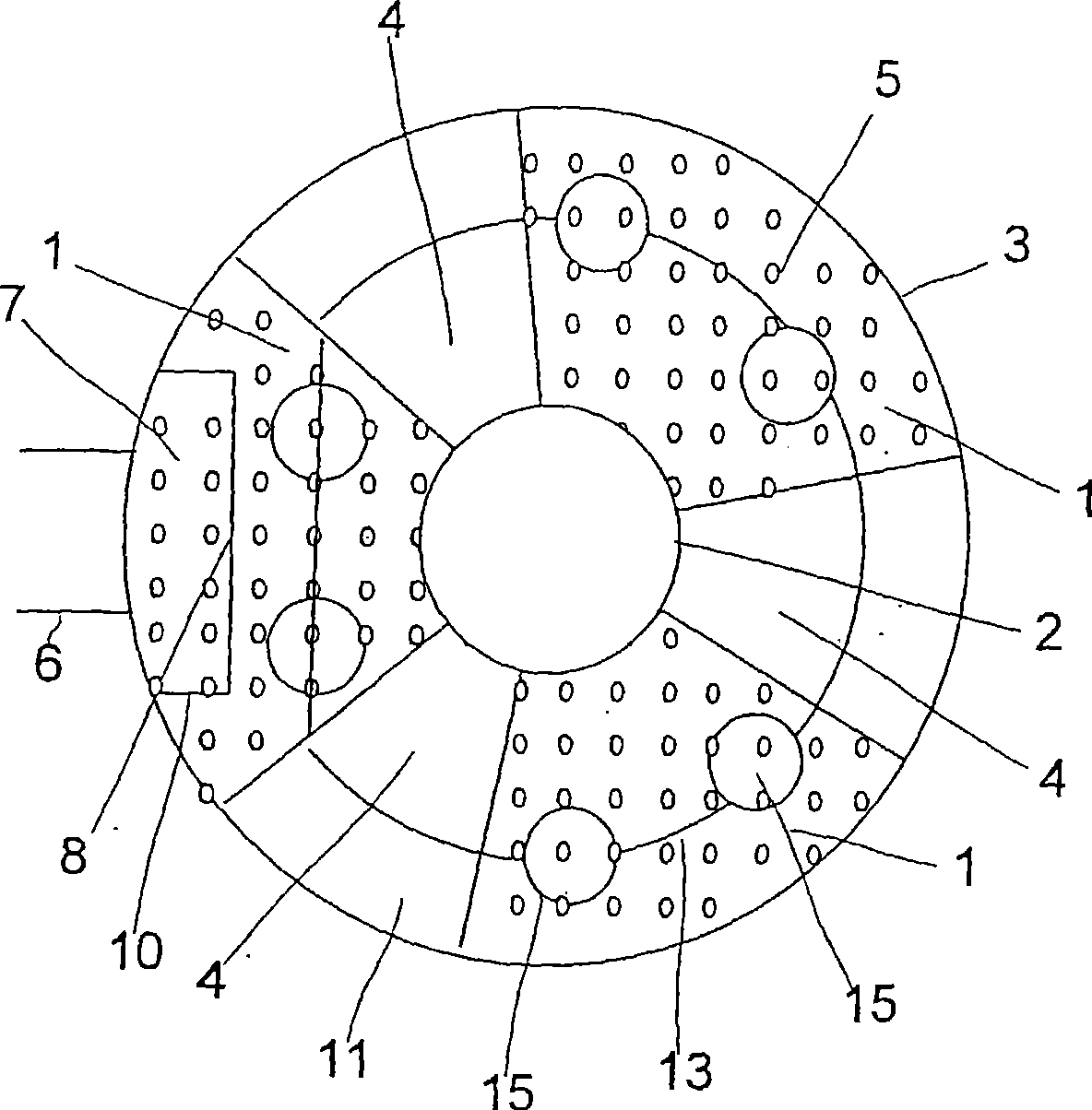
[0026] figure 1 shows a top view of a conventional liquid distributor for a wound heat exchanger used, for example, as a liquefier in an LNG base-type production plant. The liquid distributor has three pie-segment-shaped perforated bottom plates 1 which are arranged uniformly around the core tube 2 of the heat exchanger and extend as far as the cylindrical shell 3 of the heat exchanger. A plurality of tubes are wound on the core tube 2 and are guided through the distributor in the open regions 4 between the individual perforated base plates 1 .

[0027] The perforated bottom plate 1 is provided with a plurality of drip openings 5 ​​through which the liquid on the perforated bottom plate 1 can drip onto the tube bundle located below.

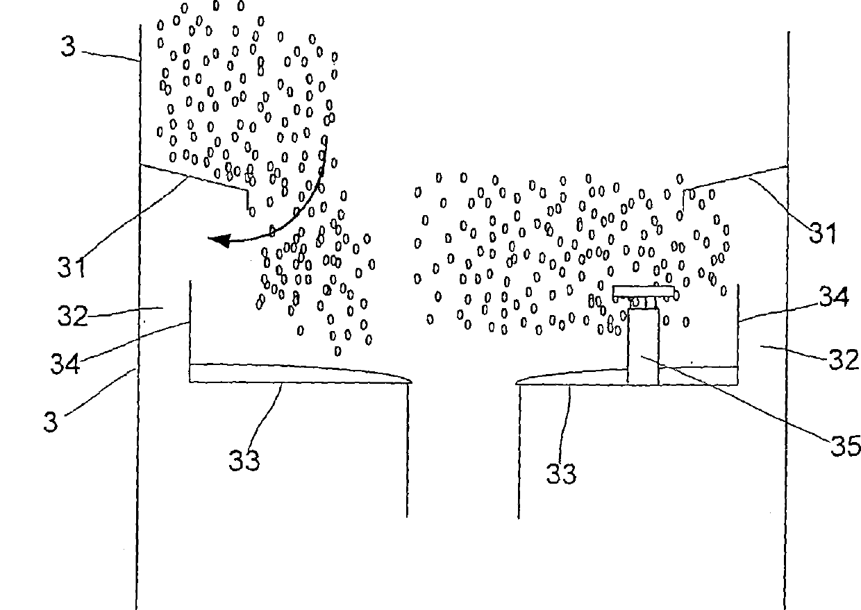
[0028] The supply of liquid takes place via a ring pre-distributor as in the figure 2 and image 3 as shown schematically. The annular predistributor has a lateral liquid inlet 6 which opens into a surge tank 7 . The side 8 of the buffer bo...


PUM


Abstract

The invention relates to a rolled heat exchanger comprising several pipes wound around a central pipe, a casing delimiting the external space around the pipes and a liquid distributor for distributing liquid in the external space. According to the invention, the liquid distributor is embodied in the form of a pipe manifold comprising a main channel (21) and several distributing arms (22) which are fluidically connected thereto.

Description

technical field [0001] The invention relates to a wound heat exchanger having a plurality of tubes wound on a core tube, having a shell delimiting an external space surrounding the tubes and having a liquid distribution device for distributing liquid in the external space A device, wherein the liquid distributor is configured as a pipe distributor having a main channel and a plurality of distribution arms that are in flow connection with the main channel. Such a heat exchanger is known from DE 2835334 A1. Background technique [0002] In the LNG base type production facility, natural gas is continuously liquefied in large quantities. The liquefaction of natural gas is mostly carried out by exchanging heat with the cold carrier in the wound heat exchanger. [0003] In a wound heat exchanger, multiple layers of tubes are wound around a core tube. A medium is guided through the individual tubes which, during the heat exchange, joins the medium flowing in the space between th...

Claims


Application Information

Patent Timeline
IPC IPC(8): F28D7/02F28F25/02F25J3/00
CPCF25J5/002F25J2290/32F28F9/026F28D7/024F28D7/04
Inventor 克里斯蒂安·克贝尔赫尔穆特·克赖斯安东·莫尔曼弗雷德·施泰因鲍尔
Owner LINDE AG
Why Eureka
Try Eureka