Armature, rotating electric machine, DC motor, and brushless motor

A technology of armature and armature iron core, applied in the field of armature, rotating electrical machine, DC motor and brushless motor, can solve the problem of increasing the number of armature iron core parts

Inactive Publication Date: 2007-09-05
ASMO CO LTD
View PDF3 Cites 5 Cited by
  • Summary
  • Abstract
  • Description
  • Claims
  • Application Information

AI Technical Summary

Problems solved by technology

[0008] However, since the armature core has connection p

Method used


Image

  • Armature, rotating electric machine, DC motor, and brushless motor
  • Armature, rotating electric machine, DC motor, and brushless motor
  • Armature, rotating electric machine, DC motor, and brushless motor

Examples


Embodiment Construction

[0056] Hereinafter, a first embodiment of the present invention will be described with reference to FIGS. 1 to 10 .

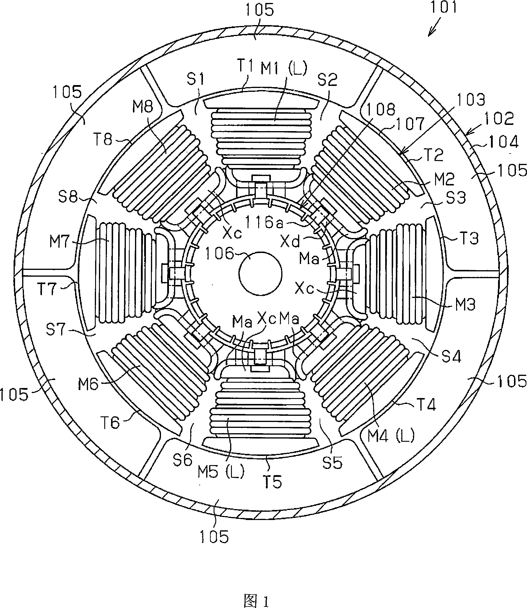
[0057] As shown in FIG. 1 , a DC motor 101 as a rotating electrical machine has a stator 102 and an armature 103 as a rotor. The stator 102 has a substantially cylindrical yoke cover 104 and a plurality of magnets 105 fixed to the inner peripheral surface of the yoke cover 104 at equal angular intervals. In this embodiment, the number of magnets 105 is six, constituting six poles, and the number of magnetic poles is six.

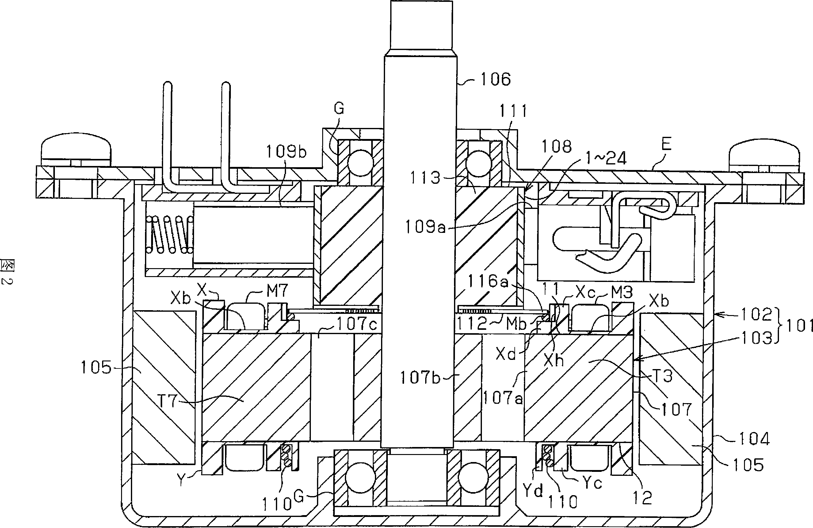
[0058] As shown in FIG. 1 and FIG. 2 , the armature 103 includes a rotating shaft 106 , an armature core 107 fixed on the rotating shaft 106 , and a commutator 108 also fixed on the rotating shaft 106 . As shown in FIG. 2 , both ends of the rotating shaft 106 are rotatably supported by a pair of bearings G held by the yoke cover 104 and the end cover E that closes the opening of the yoke cover 104 . An anode-side brush 109a and a cathode-si...


PUM


Abstract

Windings (M1 to M8) are wound by concentrated winding around teeth (T1 to T8) of an armature core (107, 317) to which insulators (X, Y) are attached. A feeding member (108, 314) for feeding current to the windings (M1 to M8) has a connection section (116a, 332a). Separation sections (Xc) provided to the insulator (X) are arranged on teeth (T1 to T8). The separation sections (Xc) separate each of the windings (M1 to M8) into first and second portions (Ma, L). The connection section (116a, 332a) is electrically connected to the first portion (Ma). As a result, the windings can be easily connected to the feeding member while preventing damage to the windings.

Description

technical field [0001] The present invention relates to armatures, rotating electrical machines, DC motors and brushless motors. Background technique [0002] An armature of a conventional DC motor has a winding and a commutator electrically connected to the winding. In the DC motor disclosed in Patent Document 1, the free end of the lead wire end extends from the wire wound around the armature core. The free end is connected to a connecting portion provided on the commutator piece. [0003] However, in the above-mentioned DC motor, the step of connecting the free end of the lead wire extending from the winding to the connecting portion of the commutator is an independent step different from the step of winding the wire around the armature core. That is, the work of connecting the wires to the connecting portion of the commutator is cumbersome. [0004] In addition, the wire end is connected to the connection part of the commutator by, for example, soldering at a position...

Claims


Application Information

Patent Timeline
IPC IPC(8): H02K3/52H02K23/04H02K1/14H02K23/26H02K3/18
Inventor 中野芳規関明彦田尾吉隆影山良平杉島一志伊藤靖英桑野雅幸山本敏夫泉和幸
Owner ASMO CO LTD
Why Eureka
Try Eureka