Micro-domain heating apparatus

A heating device and micro-domain technology, which is applied to measurement devices, instruments, scientific instruments, etc., can solve the problems of large temperature difference in the heating area, and achieve the effects of large working area, simple heating device, and large working flow rate range.

Inactive Publication Date: 2007-10-31
IND TECH RES INST
View PDF0 Cites 3 Cited by
  • Summary
  • Abstract
  • Description
  • Claims
  • Application Information

AI Technical Summary

Problems solved by technology

However, due to the heating in a small area, if the length, width and thickness of the resistance

Method used


Image

  • Micro-domain heating apparatus
  • Micro-domain heating apparatus
  • Micro-domain heating apparatus

Examples


Embodiment Construction

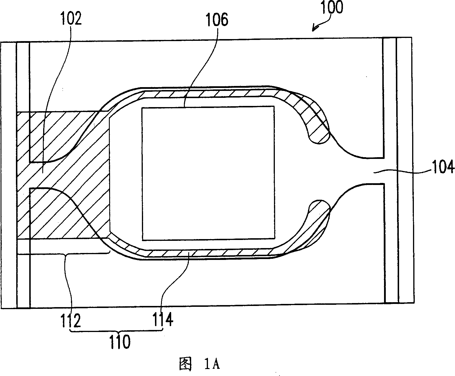
[0026] The micro-domain heating device of the present invention is used for heating microfluidic chips, and its design concept is to divide the whole micro-domain heating device into a preheating part and a heating part. Wherein, the preheating part corresponds to the fluid inlet of the aforementioned microfluidic chip, so that the temperature of the fluid is raised before entering the working area of ​​the microfluidic chip. The heating part surrounds the working area of ​​the microfluidic chip, so as to heat the fluid in the working area to a specific uniform temperature. Several embodiments are given below as examples, but it does not mean that the device of the present invention is limited to these embodiments.

[0027] FIG. 1A is a structural diagram of a microfluidic chip with a micro-domain heating device according to the first embodiment of the present invention.

[0028] Referring to FIG. 1A , there is a microfluidic chip 100 in this embodiment, and the microfluidic ...


PUM


Abstract

This invention relates to one micro zone heating device for one micro flow chip, which comprises exit, entrance and one work area in between, wherein the above heating device comprises one pre-heating part and one heating part; the pre-heating part is set relative to the front micro flow chip and the heating part is connected to the pre-heating part around micro flow chip work area with even temperature distribution.

Description

technical field [0001] The present invention relates to a heating module, and in particular to a microscale heating module. Background technique [0002] There are many applications of microfluidic technology in traditional biochemical analysis, such as micropumps, microvalves, microfilters, micromixers, micropipes, microsensors and other components, most of which are concentrated on biochemical chips for sample pretreatment, mixing , transmission, separation and detection procedures. Among them, the use of microfluidic chips for biomedical detection or analysis has the advantages of reducing experimental errors in manual operations, improving system stability, reducing energy consumption and sample consumption, and saving manpower and time. [0003] Generally speaking, the microfluidic chip uses semiconductor etching technology to carve tiny channels on glass or plastic substrates, allowing the sample to flow in the tiny channels and complete chemical reactions such as sol...

Claims


Application Information

Patent Timeline
IPC IPC(8): G01N31/00G01N35/00
Inventor 陈志坚吴志文
Owner IND TECH RES INST
Why Eureka
Try Eureka