Device that can illuminate in a certain dirction

A technology for directional lighting and lighting devices, which is applied to fixed lighting devices, lighting devices, lighting auxiliary devices, etc., can solve the problems of not ensuring safety and stability, interfering with the appearance of lighting devices, and lack of design.

A technology for directional lighting and lighting devices, which is applied to fixed lighting devices, lighting devices, lighting auxiliary devices, etc., can solve the problems of not ensuring safety and stability, interfering with the appearance of lighting devices, and lack of design.

CN101070953AActive Publication Date: 2007-11-14IGUZZINI ILLUMINAZIONE

Image

  • Device that can illuminate in a certain dirction
  • Device that can illuminate in a certain dirction
  • Device that can illuminate in a certain dirction

Examples


Embodiment Construction

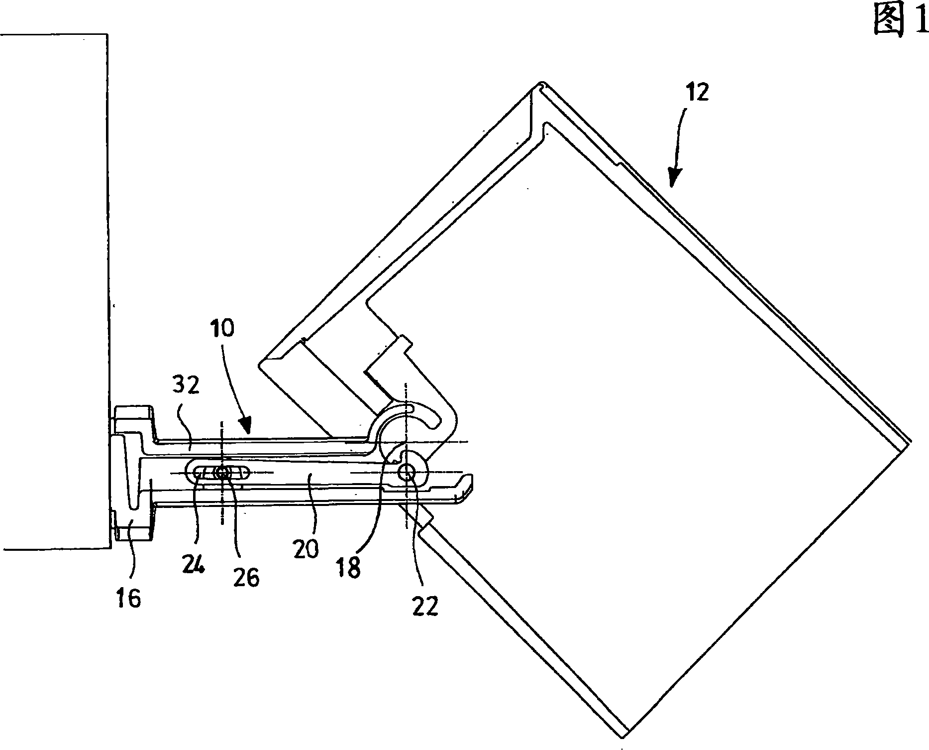
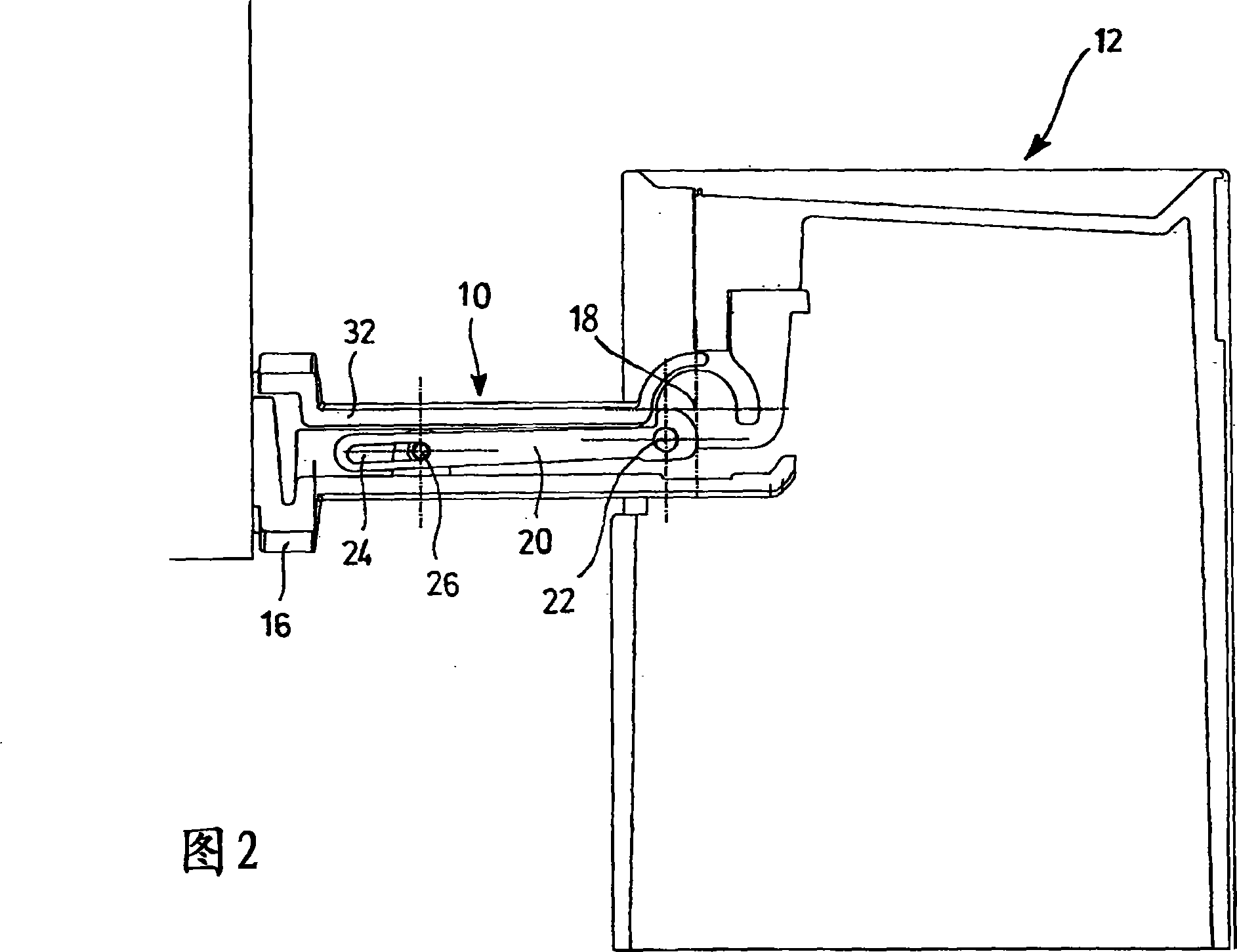
[0013] With particular reference to Figures 1 and 2, which schematically show an orientable lighting device comprising a support arm 10 supporting and fastened to at least one projection device or light space 12, said at least one At least one light source (not shown) is constructed in the projection device or lamp space 12 .

[0014] The light sources contained in the lamp space 12 consist, for example, of discharge lamps or halogen lamps which are energized at supply voltage or low voltage by interposing a suitable transformer.

[0015] In addition to the light source, the lamp space 12 contains in its interior all elements necessary for the correct functioning of the lighting device, i.e. possible reflective walls and / or covers, reactors, transformers and various electrical components, while at least one recess is constructed inside it. The slot (FIG. 4) and the support arm 10 for the passage of the power cord are adapted to be fixed directly by means of its connecting port...


PUM


Abstract

An orientable lighting appliance of the type comprising a supporting arm (10), suitable for installation on a fixed structure, which supports, by means of a hinge (18), at least one lamp space (12) inside which there is at least one light source. The lighting appliance also comprises at least one lever (20) slidingly coupled with the supporting arm (10) and constrainable thereto, hinged on the lamp space (12) by means of a pin (22) having a parallel and distanced rotation axis with respect to the rotation axis of the hinge (18).

Description

technical field [0001] The present invention relates to orientable lighting devices which are particularly, but not exclusively, adapted to be mounted on walls, having important utility and ease of use. Background technique [0002] Lighting devices are known and they basically consist of a projection device that is rotatable about an arm adapted to be mounted on a wall or ceiling. These lighting devices are generally used to directly and clearly illuminate a specific object and their special feature is that they can be easily orientated according to the needs of use. [0003] However, one of some disadvantages of orientable lighting devices according to the prior art is that they are not designed with suitable means for holding the projection device once the desired lighting position has been determined. In fact, in these lighting devices, this holding is achieved simply by the friction generated by the articulated combination between the arm fixed to the wall and the proj...

Claims


Application Information

Patent Timeline
14 Nov 2007
Publication
CN101070953A
IPC
F21S8/00; F21V21/30; F21V21/14
CPC
F21V23/002; F21S8/036; F21S8/043; F21V21/116; F21V21/30
Inventors
马西莫·佳塔里