Switching device with actuating component

A technology of switch devices and operating parts, which is applied in the direction of electric switches, protection switches, emergency protection devices, etc., and can solve problems such as undesired functionality

Active Publication Date: 2012-06-27
SIEMENS AG
View PDF0 Cites 0 Cited by
  • Summary
  • Abstract
  • Description
  • Claims
  • Application Information

AI Technical Summary

Problems solved by technology

However, this functionality is not desired, so that the position of the operating element must be changed in order to maintain the usual state position of the operating element

Method used


Image

  • Switching device with actuating component
  • Switching device with actuating component
  • Switching device with actuating component

Examples


Embodiment Construction

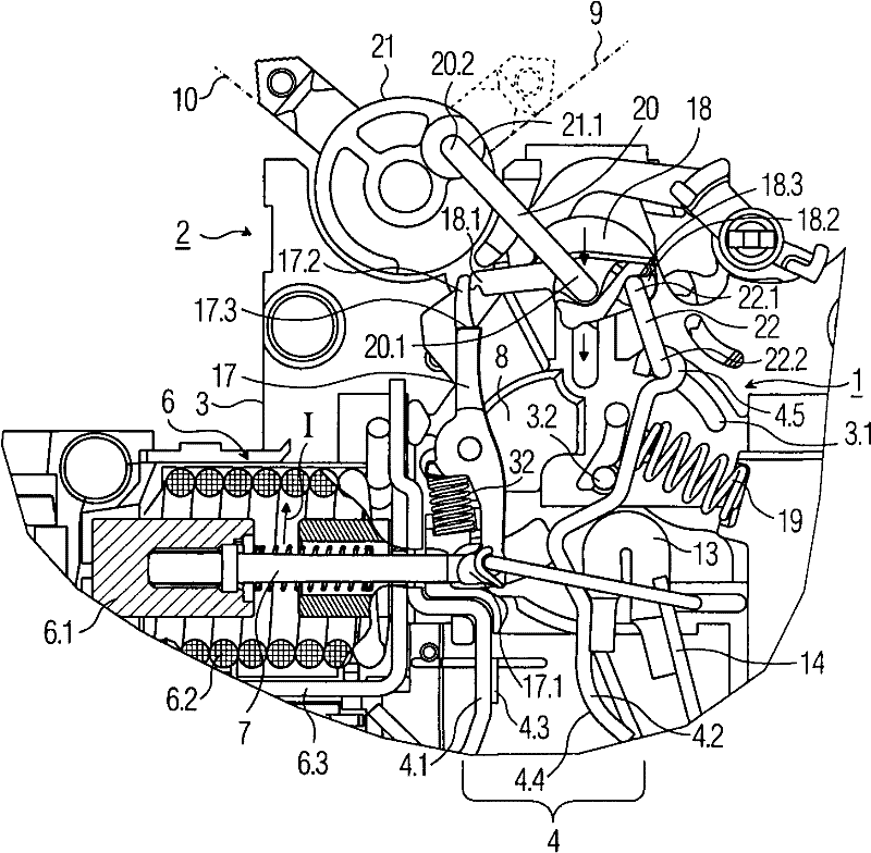
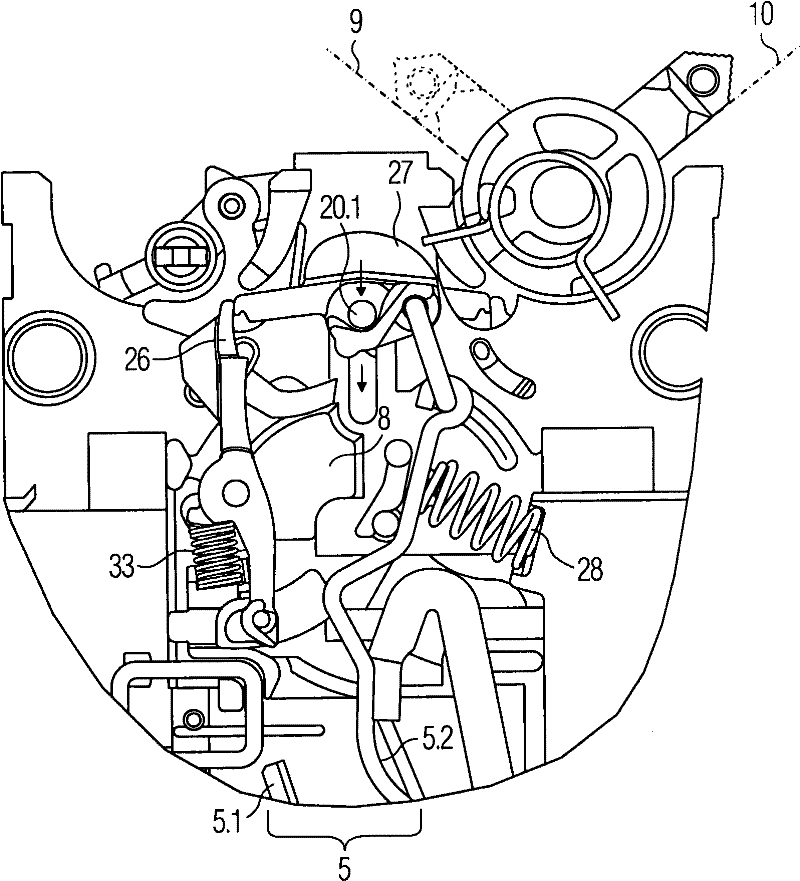
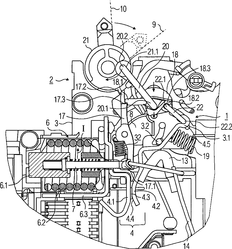
[0011] exist Figures 1 to 11 A switching device 1 is shown as part of a switching device 2 . The switchgear 2 is designed as a line protection switch and is suitable as a switchgear for those used in AC networks. The switching device 2 has a housing width of 18 mm, which corresponds to a so-called distribution unit in the area of ​​a series arrangement. The components of the transmission load current part of the device (especially the components of the phase conductor or the L part) and the components of the return current part of the device (especially the components of the neutral line or the N part) are set in the distribution unit; here, the two The individual switching mechanical parts and switching contact parts of each device part are arranged in the housing 3 in a mirror-image alternate manner and insulated from each other. In addition to housings with one distribution unit, housings with a housing width of 36 mm and two distribution units are also possible, which c...


PUM


Abstract

The invention provides a switching device (1) with an operation piece (21) to change position on keeping functional character. Firsly a rotary claw (18) is mounted to connect or release the said claw on a rotary releasing lever (17), and a transmission bent matter (20) is mounted, which can is rotatablely mounted at the operation piece (21) and claw (18), wherein on one hand a rotary contact carrier (4.2) is designed to be one part of switchpoint (4) for contacting the fixed contact carrier (4.1), on the other hand a joint bent matter (22)is rotatablely mounted at oblique contact carrier (4.2) and claw (18), wherein the claw (18) can move like thif at the turning pivot thereof (20.1), namely the distance between the operation piece (21) and claw (18) changes based on the position of the operation piece (21).

Description

technical field [0001] The invention relates to a switching device with an operating element. Background technique [0002] Switching devices of this type are usually part of a protective switchgear with a housing width of 18 mm, which also has a separate distribution unit 1TE in which the first switching point for the phase conductor and the neutral conductor The other switching point of each of them occupies half of the distribution unit of the device width. Each connection side of the protective switching device has two connection points offset in height relative to one another, one of which is arranged in the circuit of the current conductor and the other in the circuit of the neutral conductor. When viewing the upper connection side from the front of the device, the connection position of the neutral line is located in the lower right area of ​​the connection side, on the contrary, the connection position of the phase conductor is located in the upper left area of ​​th...

Claims


Application Information

Patent Timeline
Patent Type & Authority Patents(China)
IPC IPC(8): H01H71/10
CPCH01H2011/0025H01H71/002H01H71/528
Inventor 温弗里德·菲尔林
Owner SIEMENS AG
Why Eureka
Try Eureka