Method and device for braking the rotor of a wind energy plant

A technology of wind power equipment and driving devices, which is applied in the control of wind power engines, mechanical equipment, wind power engines, etc., can solve the problems of high assembly and operation costs, and achieve the effect of reliable interruption

Inactive Publication Date: 2008-03-12
WINDTEC CONSULTING GMBH
View PDF1 Cites 2 Cited by
  • Summary
  • Abstract
  • Description
  • Claims
  • Application Information

AI Technical Summary

Problems solved by technology

Therefore, the disadvantages of the device according to WO 99 / 23384 A1 are that the large arrows lead to higher assembly and operating costs, or that the battery is used in the hub for supporting the rotor blades to be swiveled into the sail position by the rotor blade drive Necessity in

Method used


Image

  • Method and device for braking the rotor of a wind energy plant

Examples


Embodiment Construction

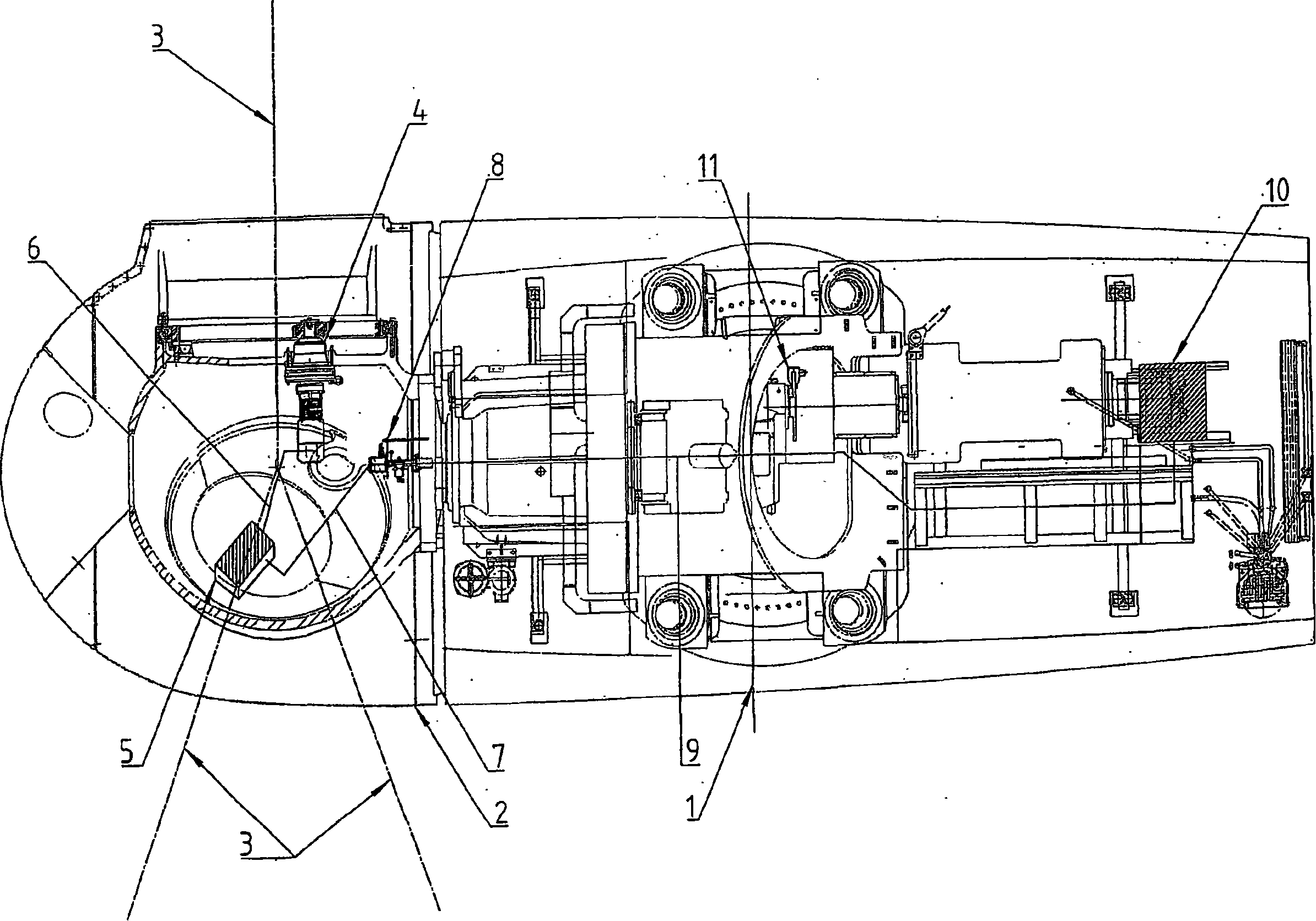
[0011] The figure schematically depicts a nacelle 1 of a wind power plant, on which a hub 2 is rotatably mounted. A schematically depicted rotor blade 3 is rotatably mounted on the hub 2 via its axis of rotation. In order to rotate the rotor blades 3 , each rotor blade 3 is provided with a drive consisting of an electric motor 4 and a frequency converter 5 . Each electric motor 4 is equipped with a lock which, in the activated state, prevents the rotor blade 3 from rotating into the operating position, but allows the rotor blade 3 to rotate continuously or discontinuously into the sail position. In the inactive state the lock is inactive, ie rotation of the rotor blade 3 in all directions is possible. The lock can be designed and operated as described in WO 99 / 23384 A1, for example. However, the lock can also be designed in such a way that it catches and blocks the rotor blades 3 only in the sail position, so that they rotate back into the operating position.

[0012] Each ...


PUM


Abstract

The invention relates to a method and device for braking the rotor of a wind energy plant, comprising rotor blades (3) mounted to rotate on the rotor with electrical devices in the rotor hub (2), such as an actuator (4, 5) for the rotation of the rotor blades (3), whereby on drop-out of the power supply to the electrical devices (4, 5), a rotor brake is activated (11), whereupon the rotor blades (3) as a result of the braking torque of the rotor brake (11) are rotated into the feathered position by means of the inertia thereof.

Description

technical field [0001] The invention relates to a device for adjusting a rotor blade rotatably supported on a rotor hub of a wind power installation, comprising: an electrical device in the rotor hub, such as a drive device for rotating the rotor blade; a lock connected to the rotor blade a lock which is automatically activated in the event of a failure of the power supply to the drive or a failure of the drive and which, in the activated state, prevents the rotation of the rotor blades into the operating position; and a rotor brake and an emergency power supply. [0002] Furthermore the invention relates to a method for braking a rotor of a wind power plant, comprising: rotor blades rotatably supported on the rotor; electrical means in the rotor hub, such as drive means for rotating the rotor blades; A stop connected to the blades, which is automatically activated in the event of a failure of the power supply to the drive or a failure of the drive and which, in the activated ...

Claims


Application Information

Patent Timeline
IPC IPC(8): F03D7/02
CPCF05B2270/107Y02E10/723F03D7/0248F05B2260/76F05B2260/79F05B2260/75F05B2260/78F03D7/0224Y02E10/72F03D7/02
Inventor G·黑亨伯格
Owner WINDTEC CONSULTING GMBH
Why Eureka
Try Eureka