An Overvoltage Protection Device with Leakage Current Cutoff

A protection device, overvoltage technology, applied to emergency protection circuit devices for limiting overcurrent/overvoltage, emergency protection devices for automatic disconnection, overvoltage protection resistors, etc., can solve the problem of expensive tripping devices and other issues

Inactive Publication Date: 2019-03-05
PHOENIX CONTACT GMBH & CO KG
View PDF3 Cites 0 Cited by
  • Summary
  • Abstract
  • Description
  • Claims
  • Application Information

AI Technical Summary

Problems solved by technology

Along with technical challenges, this expense is also a cost driver, making the corresponding tripping devices very expensive overall

Method used


Image

  • An Overvoltage Protection Device with Leakage Current Cutoff

Examples


Embodiment Construction

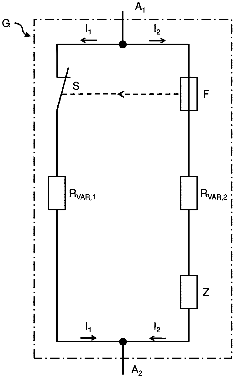
[0025] figure 1 An exemplary schematic diagram of an exemplary embodiment of an overvoltage protection device with leakage current cut-off is shown. It includes the first current branch I 1 and the second current branch I 2 of parallel circuits.

[0026] The first current branch I 1 comprising a switching element S and a first non-linear resistance element R in series var,1 . The second current branch I 2 Including a fuse element F with signal output characteristics connected in series and a second non-linear resistance element R var,2 and a composite resistor Z.

[0027] The switch element S and the fuse element F with signal output characteristics are urged to cooperate with each other, so that the switch element S is controlled by the state change output of the fuse element F with signal output characteristics to perform open circuit switching.

[0028] In this way, a reliable cut-off can be ensured, as will be explained below.

[0029] In the first current branch ...


PUM


Abstract

The invention discloses an overvoltage protection device with leakage current cut-off, which has a first current branch (I 1 ) and the second current branch (I 2 ) of the parallel circuit, the first current branch (I 1 ) has a series connected switching element (S) and a first nonlinear resistive element (R var,1 ), the second current branch (I 2 ) has a series-connected fuse element (F) with signal output characteristics and a second non-linear resistive element (R var,2 ) and a composite resistor (Z), the switching element (S) is controlled by the signal output of the fuse element (F) for open-circuit switching.

Description

technical field [0001] The invention relates to an overvoltage protection device with leakage current cut-off. Background technique [0002] The most widespread types of overvoltage protection devices have undesirable leakage currents due to aging and / or operating outside of their specified operating voltages. [0003] On the one hand, these leakage currents lead to higher energy costs, and on the other hand, these leakage currents also lead to heating of the associated overvoltage protection device. This heating can be very intensive, so that it may cause further damage or destruction of the overvoltage protection device itself and surrounding components, and even cause a fire. [0004] To address these negative effects, various constructions have been proposed in the past, with which a failed overvoltage protection device can be disconnected from the power supply network in order to prevent unacceptable heating or destruction of the overvoltage protection device. [0005...

Claims


Application Information

Patent Timeline
Patent Type & Authority Patents(China)
IPC IPC(8): H02H9/04
CPCH02H9/042H02H9/043H01H37/761H01C7/12H02H9/02H02H5/04H02H3/20
Inventor 马丁·斯瑞伍约阿希姆·沃斯振
Owner PHOENIX CONTACT GMBH & CO KG
Why Eureka
Try Eureka