Overvoltage protection device

A protection device, overvoltage technology, applied in circuit devices, emergency protection circuit devices, emergency protection circuit devices for limiting overcurrent/overvoltage, etc., can solve problems such as insufficient use

Inactive Publication Date: 2012-08-01
PHOENIX CONTACT GMBH & CO KG
View PDF6 Cites 2 Cited by
  • Summary
  • Abstract
  • Description
  • Claims
  • Application Information

AI Technical Summary

Problems solved by technology

For this, error notification via a separate remote communication contact (Fernmeldekontakt) is not sufficient, as is an optical status display directly on the overvoltage protection device

Method used


Image

  • Overvoltage protection device
  • Overvoltage protection device
  • Overvoltage protection device

Examples


Embodiment Construction

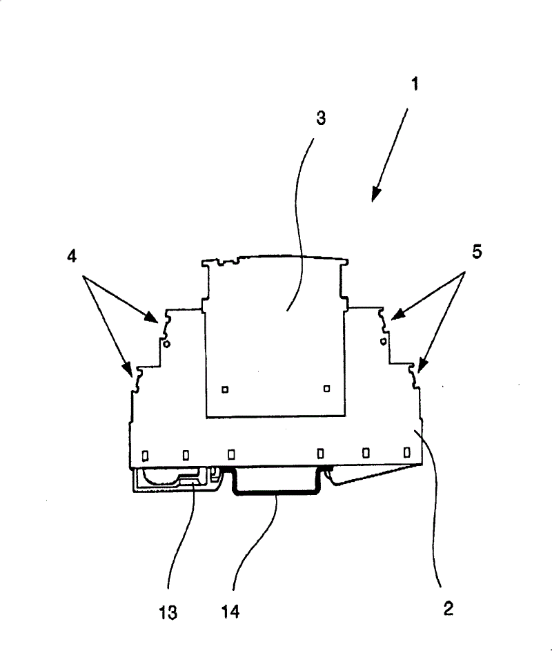
[0030] figure 1 A schematic diagram of an overvoltage protection device 1 is shown, which is configured as a switch cabinet module and has a device bottom 2 and a device upper part 3 that can be inserted on the device bottom 2. The bottom of the device has input terminals 4 and output terminals 5 on its two end faces. The input terminals 4 and output terminals 5 are preferably configured as screw terminals or traction spring terminals and are arranged up and down in staggered positions in two rows. In order to be able to simply insert the upper part 3 of the device on the bottom 2 of the device, a socket is formed in the bottom 2 of the device and corresponding pins are arranged in the upper part 3 of the device, wherein the socket is conductively connected to the input terminal and the output terminal 4, 5. The pins are electrically conductively connected to the protective element 6 provided in the upper part 3 of the device.

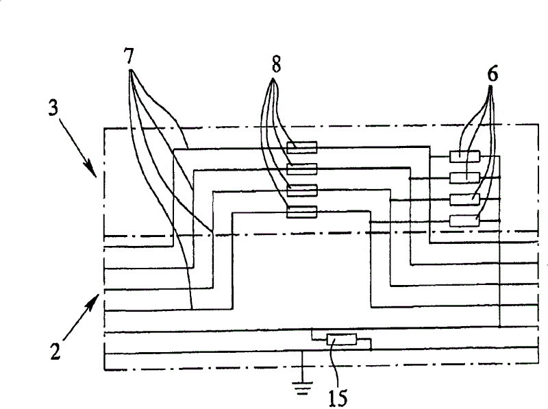
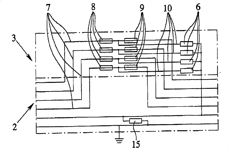
[0031] Figure 2 to Figure 5 Show schematically fig...


PUM


Abstract

The invention relates to and describes an overvoltage protection device, particularly for the protection of electric low-voltage installations, comprising a unit base (2) and at least one unit top (3) that can be placed on the unit base (2). The unit base (2) comprises input and output terminals (4, 5) for electric conductors and contact elements, particularly in the form of a socket, connected to the input and output terminals (4, 5). The unit top (3) comprises counter contact elements, particularly configured as pins, corresponding to the contact elements and at least one protective element(6) connected between two counter contact elements, particularly a varistor. The overvoltage protection device can thus be used also where unacceptable operating conditions have to be transmitted directly via the protected line system, for example in the area of train signal technology. At least one line path (7) runs between two input and output terminals (4, 5) associated with each other via the unit top (3) such that the line path (7) is disconnected when the unit top (3) is not connected, and such that in at least one line path (7) in the unit top (3) at least one disconnecting element (8) is disposed such that in case the disconnecting element (8) is actuated, due to an unacceptable operating condition of the protective element (6), the respective line path (7) is disconnected even when the unit top (3) is connected.

Description

Technical field [0001] The present invention relates to an overvoltage protection device, especially for protecting low-voltage electrical equipment. The overvoltage protection device is composed of a device bottom and at least one device upper part that can be inserted into the device bottom, wherein the device bottom has a conductive body Input and output terminals and contact elements connected with the input and output terminals, specially configured as sockets, and wherein the upper part of the device has a mating contact element corresponding to the contact element, specially configured as a pin, and at least one mating contact The connection between the elements, especially the protective element of the varistor. Background technique [0002] The lines of measurement technology, control technology and regulation technology form the nerve line of industrial equipment. The electronic measuring circuits, control circuits, regulating circuits, and switching circuits connected...

Claims


Application Information

Patent Timeline
Patent Type & Authority Patents(China)
IPC IPC(8): H02H9/04H01T4/06
CPCH01T4/06H02H9/042
Inventor G·沃尔夫B·弗里特泽迈耶M·桑道C·瓦格纳
Owner PHOENIX CONTACT GMBH & CO KG
Why Eureka
Try Eureka