Shuttering member for in situ concrete

A technology of formwork components and cast-in-place concrete, which is applied in the direction of building components, formwork/formwork/work frames, and construction components on-site preparation, which can solve the problems of increasing construction costs and reducing construction speed

Inactive Publication Date: 2008-05-28
湖南邱则有专利战略策划有限公司
View PDF5 Cites 2 Cited by
  • Summary
  • Abstract
  • Description
  • Claims
  • Application Information

AI Technical Summary

Problems solved by technology

However, after this polyhedral solid lightweight material member is applied to the cast-in-place concrete floor, it still needs to support the construction formwork, which reduces the construction speed and increases the construction cost. for urgent need

Method used


Image

  • Shuttering member for in situ concrete
  • Shuttering member for in situ concrete
  • Shuttering member for in situ concrete

Examples


Embodiment Construction

[0038] The present invention will be further described below in conjunction with the accompanying drawings and embodiments.

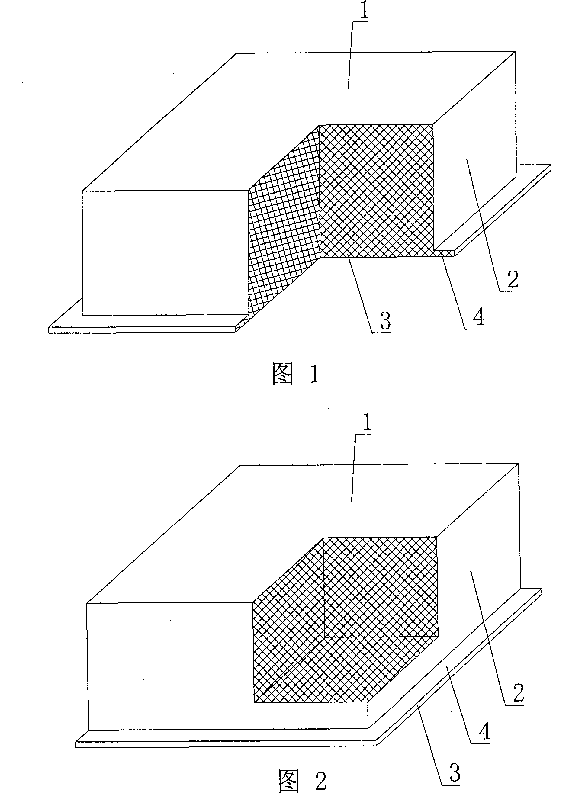
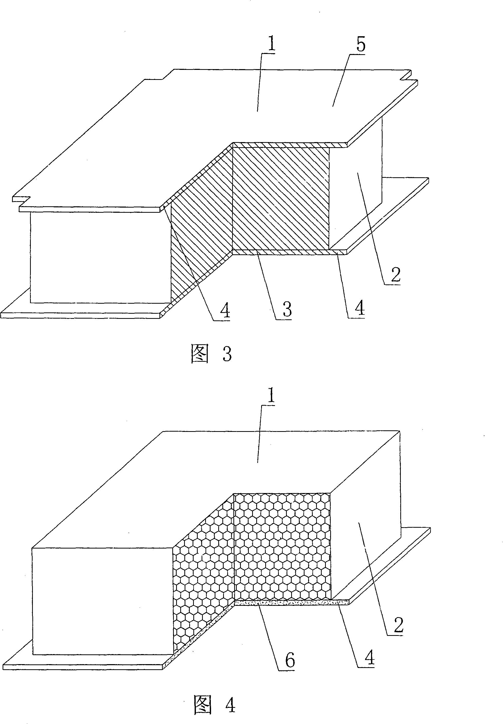
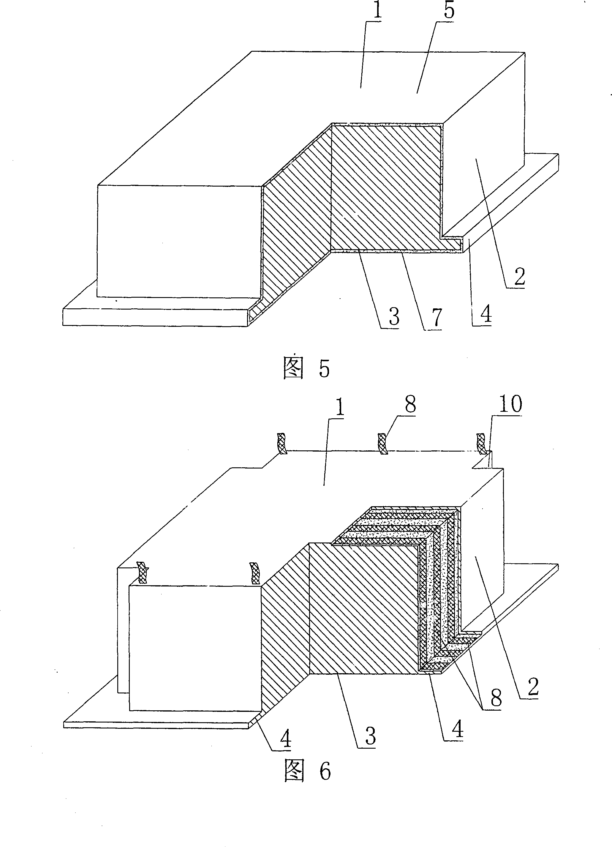
[0039] As shown in the accompanying drawings, the present invention comprises a polyhedral solid lightweight material member 1, which is characterized in that on at least one peripheral side 2 of the polyhedral solid lightweight material member 1, a pick plate 4 protrudes outward along the bottom surface 3, and the peripheral side 2 There is a pick plate 4 protruding outward from the upper edge. The pick plate 4 is a pick plate formed by setting and connecting the polyhedral solid lightweight material component 1 on the cement mortar or the cement concrete bottom plate 6. The polyhedral solid light material component 1 is foam. Plastic blocks, expanded perlite blocks, expanded vermiculite blocks, foamed or aerated concrete blocks, ceramsite concrete blocks, straw chaff cement blocks, charcoal concrete blocks or cement-bonded foam granule blocks, the oute...


PUM


Abstract

The invention relates to a cast-in-place concrete-used shuttering component, which comprises a polyhedron solid lightweight material component (1), and is characterized in that a cantilever slab (4) is extended outward along the bottom (3) on at least one all-round lateral face (2) of the polyhedron solid lightweight material component (1), the cantilever slab (4) is extended outward along the upper side on the all-around lateral face (2). The cantilever slab (4) is formed by the polyhedron solid lightweight material component (1) which is arranged and connected on cement mortar or a cement concrete bottom board (6), the polyhedron solid lightweight material component (1) is made of a foam plastic block, an expanded perlite block, an expanded vermiculite block, a foaming or aerating concrete block, a ceramicite concrete block, a straw and chaff cementitious material block, a wood coal concrete block or a cementation foam grain block. The outer surface of the polyhedron solid lightweight material component (1) is provided with an outer film layer (7). After the shuttering component is used in cast-in-situ concrete floor, the cantilever slab can be used as a formwork of a cast-in-place concrete rib between shuttering components, thereby a construction formwork can be saved, and the construction speed is improved, and the construction cost is reduced, thereby the purpose of the invention is achieved, and the invention is suitable for the employments in floors, roofs, walls, foundation bottom boards and hollow bridges of cast-in-situ reinforced concrete or inherent stress reinforced concrete.

Description

[0001] This application is a divisional application of an invention patent application with an application date of August 4, 2003, an application number of 03143753.2, and a title of "a formwork component for cast-in-place concrete". (1) Technical field [0002] The invention relates to a formwork component for cast-in-place concrete. (2) Background technology [0003] At present, the cast-in-place concrete floor is a widely used floor structure. The lightweight permanent tire mold filled in it has various hollow tubes and boxes, and the boxes are hollow or solid. For example, the patent No. ZL99249798.1, which the applicant applied for on November 29, 1999, is a utility model patent named "fiber-reinforced thin-walled member for reinforced concrete filling", which discloses a thin-walled formwork member, including an upper plate, The surrounding side walls, the lower bottom, and the upper plate, the surrounding side walls and the lower bottom form a polyhedral cavity. Anot...

Claims


Application Information

Patent Timeline
Patent Type & Authority Applications(China)
IPC IPC(8): E04B5/36E04G11/36
Inventor 邱则有
Owner 湖南邱则有专利战略策划有限公司
Why Eureka
Try Eureka