Eureka AIR delivers breakthrough ideas for toughest innovation challenges, trusted by R&D personnel around the world.

Backlight module group and fixing cap for fixing cable

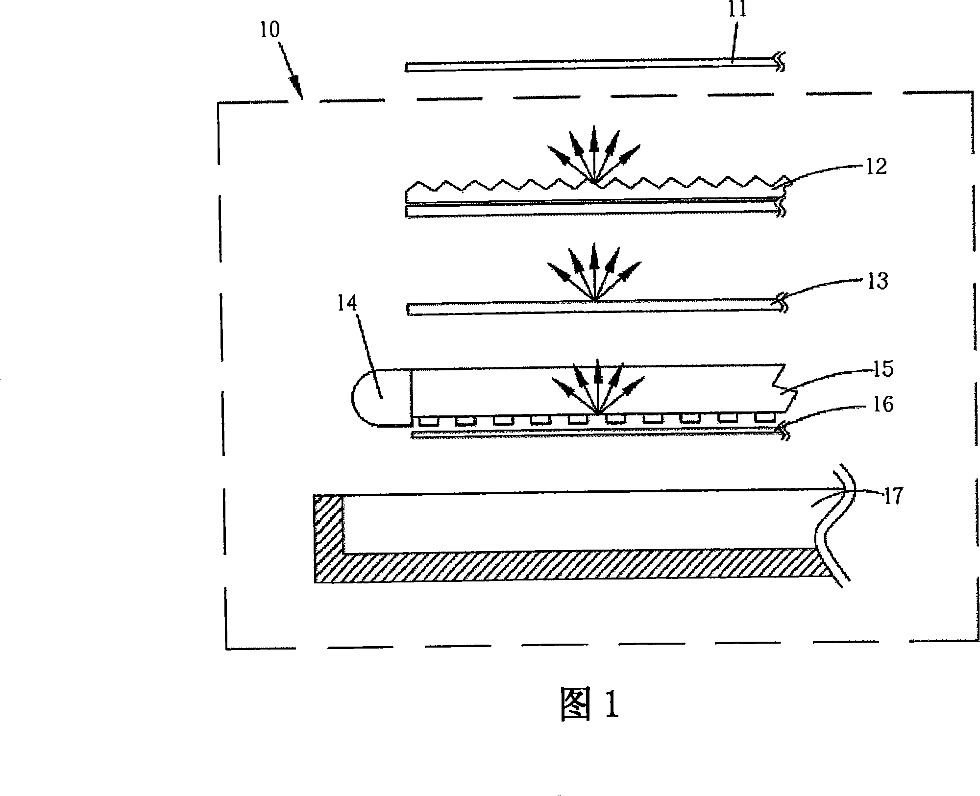
A technology for a backlight module and a fixed cover, which is applied to optics, nonlinear optics, components of lighting devices, etc., can solve the problems of loss of the fixed cover 41, loss of brightness of the liquid crystal panel, inconvenient maintenance, etc., so as to simplify the complicated dismantling process. Effect

Inactive Publication Date: 2010-09-15
AU OPTRONICS CORP
View PDF0 Cites 0 Cited by
  • Summary
  • Abstract
  • Description
  • Claims
  • Application Information

AI Technical Summary

Problems solved by technology

Depend on Figure 4 It can be seen that the fixed cover 41 in the backlight module 40 is only connected to the substrate 42 in a buckling manner, that is to say, the fixed cover 41 and the substrate 42 are detachable components, so during maintenance, the fixed cover 41 tends to be removed from the substrate 42. The base plate 42 is disassembled to facilitate subsequent maintenance. After the maintenance is completed, the fixed cover 41 is put back on the base plate 42. In this way, it will not only cause inconvenience in maintenance, but also easily cause the fixed cover due to temporary negligence. 41 lost
In addition, the fixed cover 41 and the base plate 42 are only connected in a buckling manner, so it is easy to form a gap space, and then in such as Figure 4 The phenomenon of light leakage at the opening 32 as shown detracts from the brightness of the liquid crystal panel

Method used


Image

  • Backlight module group and fixing cap for fixing cable
  • Backlight module group and fixing cap for fixing cable
  • Backlight module group and fixing cap for fixing cable

Examples


Embodiment Construction

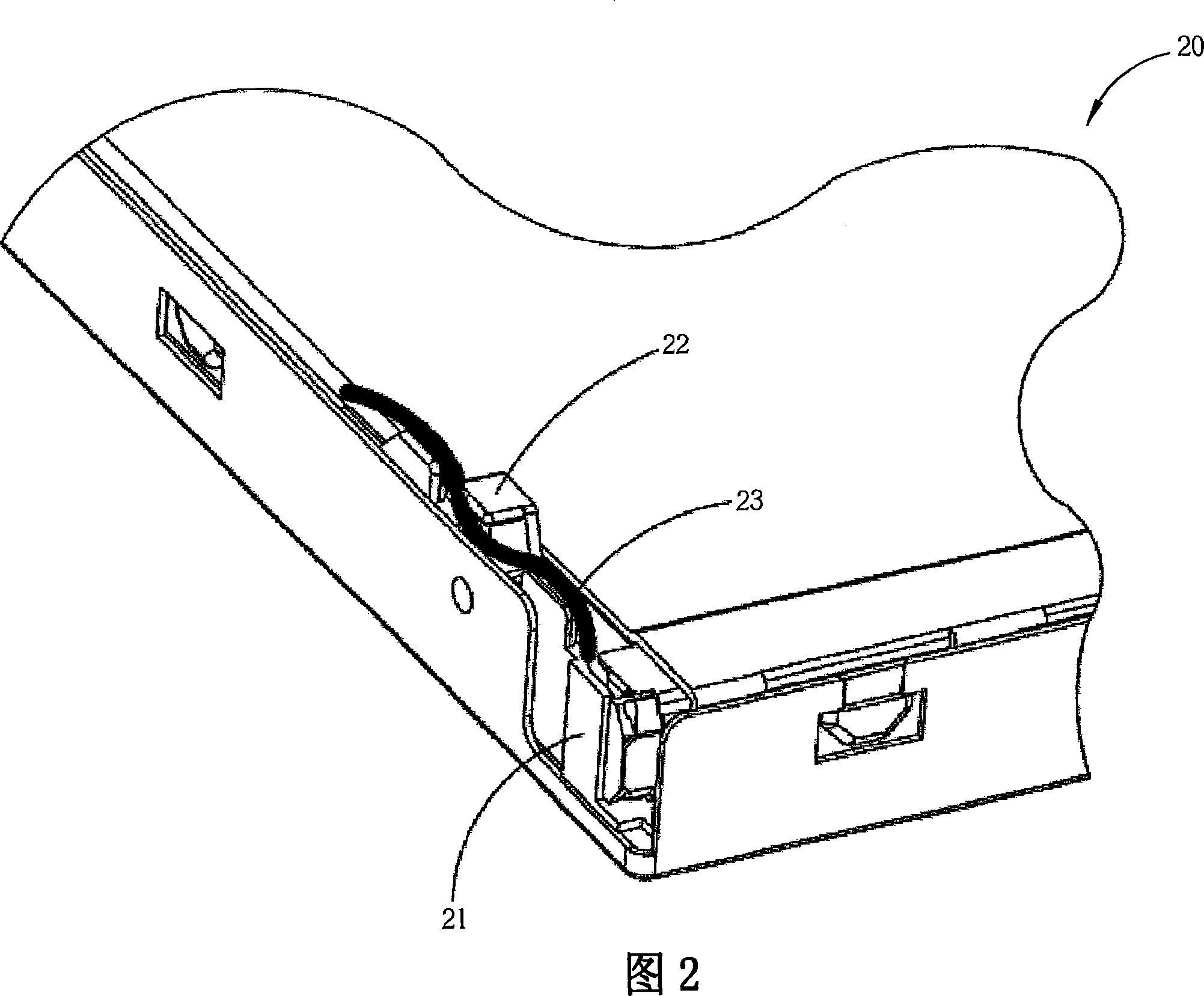
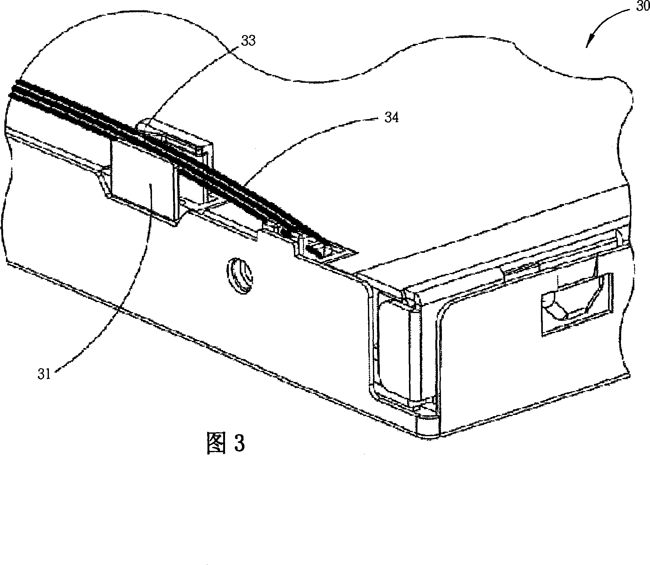
[0052] Please also see Figure 5 and Figure 6 , Figure 5 It is a partial schematic diagram of the backlight module 500 according to the first embodiment of the present invention, Figure 6 for Figure 5 Partial cross-sectional schematic diagram of the backlight module 500 . The backlight module 500 includes a first substrate 502 (such as a frame), a second substrate 504 (such as a back plate), a light source 505, a cable 506 and a fixed cover 508. The first substrate 502 has a groove 510 and a hole 512. The hole 512 formed on one side of the groove 510 . The second base plate 504 is arranged above the first base plate 502 and forms a first accommodating space with the first base plate, and the second base plate 504 has a plate body 514 and a buckle 516, the buckle hook 516 protrudes from the plate body 514 and is located on the plate The edge of body 514. The light source 505 is disposed in the first accommodating space below the second substrate 504 . The cable 506 i...


PUM


Abstract

The invention relates to a backlight module, which comprises a first substrate, a second substrate, a light source, a cable and a fixing cover, wherein the first substrate includes a groove; the second substrate includes a plate body and a hook protruding out of the plate body and is arranged above the first substrate to form a first containing space with the first substrate; the light source is disposed in the first containing space; the cable is positioned above the second substrate and is coupled with the light source; the fixing cover is arranged on the second substrate and includes a holding portion, a rotation shaft and a pin; the rotation shaft extends to the first side of the holding portion for driving the holding portion during rotation; and the pin extends to the second side ofthe holding portion and is inserted into the groove of the first substrate. Accordingly, the holding portion can form a second containing space together with the second substrate for containing the cable.

Description

technical field [0001] The invention relates to a backlight module and its fixing cover, especially to a backlight module capable of fixing cables and its fixing cover. Background technique [0002] The LCD panel (Liquid crystal display panel, LCDpanel) in the LCD is one of the key components. Since the liquid crystal itself does not emit light, the function of the backlight module is to supply sufficient brightness and uniformly distributed light source, through simple and effective light The structure is transformed into a surface light source product with high brightness and uniform luminance, and the light emitted by the backlight module is converted by the liquid crystal so that the liquid crystal display panel can display images normally. Liquid crystal display panels are now widely used in monitors, notebook computers, digital cameras, projectors and other electronic products with growth potential, especially large-sized panels such as notebook computers and LCD monit...

Claims


Application Information

Patent Timeline
Patent Type & Authority Patents(China)
IPC IPC(8): G02F1/13357F21V21/00F21V23/06
Inventor 卢芳志陈俊名黄俊玮丘振铭
Owner AU OPTRONICS CORP
Why Eureka
Eureka Blog
Learn More