Fastener

A technology for fasteners and workpieces, applied in the direction of quick-action fasteners, etc., can solve the problem that the removal force cannot be obtained

Inactive Publication Date: 2008-11-12
ILLINOIS TOOL WORKS INC
View PDF3 Cites 7 Cited by
  • Summary
  • Abstract
  • Description
  • Claims
  • Application Information

AI Technical Summary

Problems solved by technology

However, even these designs generally cannot

Method used


Image

  • Fastener
  • Fastener
  • Fastener

Examples


Embodiment Construction

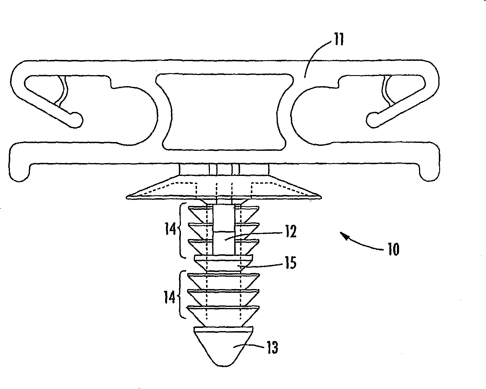
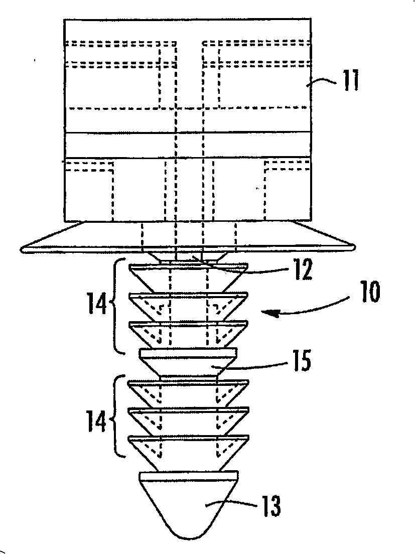
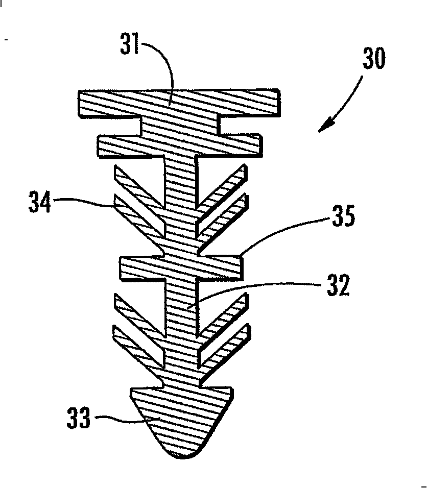
[0015] These figures show typical embodiments of the tree fastener of the present invention. These embodiments may include a fin stabilization base, also known as a fin stabilizer or force multiplier base, positioned along the fastener axis at one or Multiple requested locations. In one embodiment, the fin stabilizer is positioned a distance below the known workpiece thickness of the application and below any other components attached to the workpiece by fasteners. In this position, the fin stabilizer acts as a stop or support structure for the fins by supporting the underside of the fins to prevent the fins from turning over or being stacked one on top of the other. By strategically placing fin stabilizers along the shaft, the pullout force required to remove the fastener will be substantially increased and wobbling due to damaged fins will be prevented. It should be understood that other fin stabilizers may be used to further increase the extraction force required to extra...


PUM


Abstract

A tree-type fastener (10,30,40,55) includes one or more fin stabilizer bases (15,35,45,55) disposed on a shaft of the fastener. When the fastener is subjected to a pull-out force, the fins may be prevented from stacking up, buckling or bending by the fin stabilizer base. The stabilizer base is configured to provide no interference with a work piece when inserted in a work piece aperture. The fastener of the invention provides a high removal force to insertion force ratio and a strong, single piece device. The fastener may also be adapted for modification of new and existing tree-type fasteners.

Description

[0001] Cross References to Related Applications [0002] This non-provisional application claims the benefit of US Provisional Application 60 / 750,105, filed December 14, 2005. technical field [0003] This application relates generally to fasteners, and in particular to tree-type fasteners. Background technique [0004] Tree fasteners for joining component panels, one or more workpieces, or other structures are known. Tree fasteners are generally made of plastic material and include a plurality of standard retaining fins arranged along a longitudinal axis, the fins extending outwardly from the shaft. Fins may have shapes such as annular, flat, angled, helical or circular, to name a few. These fasteners are designed to be driven axially into holes to join one or more workpieces, and the fins may engage the edges of the holes and the surface of the workpieces to join the workpieces together. Known tree fasteners can be found, for example, in US Patent Nos. 5,468,108, 5,907,...

Claims


Application Information

Patent Timeline
IPC IPC(8): F16B21/08
Inventor 大卫·A.·谢雷克托马斯·A.·贝诺特
Owner ILLINOIS TOOL WORKS INC
Why Eureka
Try Eureka