Horizontal nib-hidden type long and short nose rail splitting method

A hidden-tip, horizontal technology, applied in tracks, roads, buildings, etc., can solve the problems of weak tip, large difference in conversion force, weakening of long-core rails, etc.

A hidden-tip, horizontal technology, applied in tracks, roads, buildings, etc., can solve the problems of weak tip, large difference in conversion force, weakening of long-core rails, etc.

CN101381977BActive Publication Date: 2011-02-02CHINA RAILWAY BAOJI BRIDGE GRP

Image

  • Horizontal nib-hidden type long and short nose rail splitting method
  • Horizontal nib-hidden type long and short nose rail splitting method

Examples


Embodiment 1

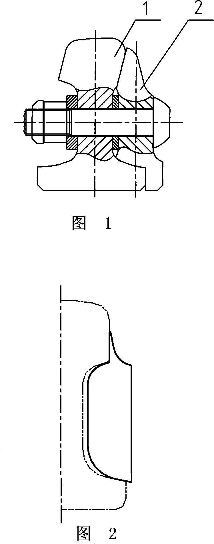
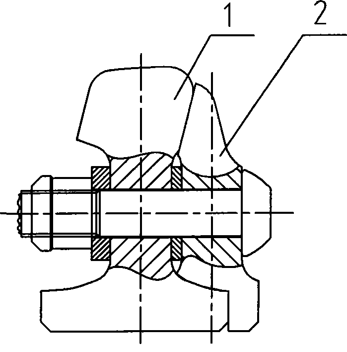
[0011] Embodiment 1: with reference to attached figure 1 . The splicing method of the long and short core rails of the horizontal hidden point type, the long core rail 1 and the short core rail 2 are connected by bolts, and the long core rail 1 is closely attached to the short core rail 2, according to the internal 1:4 oblique The horizontal cutting is 4mm, the long core rail 1 is in the range of close contact with the short core rail 2, and the working edge of the long core rail 1 is chamfered at 45°; , close to the long core rail 1, and the tip of the short core rail 2 is about 4mm wide. The difference between the processing technology of the long center rail 1 and the existing technology is that the working edge of the close-fitting section rail head is chamfered at 45°, and the existing technology and equipment can meet the processing requirements. The processing technology of the short center rail is basically the same as that of the existing turnout short center rail,...

Embodiment 2

[0012] Embodiment 2: On the basis of Embodiment 1, the splicing method of the long and short center rails of the horizontal hidden tip type, the long center rail 1 and the short center rail 2 are connected by bolts, and the long center rail 1 is connected with the short center rail 2 For the close-fitting position, cut 2mm according to the inner oblique level of 1:3, the long core rail 1 is within the range of close contact with the short core rail 2, and the working side of the long core rail 1 is chamfered at 45°; the short core rail Rail 2 closely adheres to the outer side of 1:3 oblique, and closely adheres to long core rail 1; the tip of short core rail 2 is about 3mm wide.

Embodiment 3

[0013] Embodiment 3: On the basis of Embodiment 1, the splicing method of the long and short core rails of the horizontal hidden tip type, the long core rail 1 and the short core rail 2 are connected by bolts, and the long core rail 1 is connected with the short core rail 2 For the close-fitting position, cut 5mm according to the oblique horizontal angle of 1:5, the long core rail 1 is within the range of close contact with the short core rail 2, and the working edge of the long core rail 1 is chamfered at 45°; the short core rail The edge of rail 2 is close to the outer 1:5 oblique, which is closely attached to the long core rail 1; the width of the tip of the short core rail is about 5mm.


PUM


Abstract

The invention relates to a method for splicing a horizontal tip-hidden type long point rail and a horizontal tip-hidden type short point rail. The rail body of the long point rail 1 and the rail body of the short point rail 2 are connected through a bolt; the position of the long point rail clinging to the short point rail is cut for 2 to 5 millimeters according to inner obliquity of 1:3 to 1:5; in the range of the long point rail clinging to the short point rail, the working side of a railhead of the long point rail forms a chamfer angle of 45 DEG C; a clinging side of the short point rail has outer obliquity of 1:3 to 1:5 and clings to the long point rail; and the width of the tip of the short point rail is about between 3 and 5 millimeters. The method has the following advantages: the horizontal hidden tip of the short point rail is favorable for the robustness of the short point rail structure and shortens the unsmoothness of the geometric vertical direction of the turnout on the horizontal hidden tip; at the same time, the rigidity on two sides of the long and the short point rail components tends to be consistent, which is favorable for the operation of an electrical serviceswitching system.

Description

technical field [0001] The invention relates to a scheme for long and short center rails to be spliced, and belongs to the field of splicing methods for long and short center rails of ferrous railway turnout switches. Background technique [0002] The short center rail and the long center rail of the existing turnout adopt the tip type close contact. At the position where the long center rail and the short center rail are closely attached, there is almost no cutting on the head of the long center rail, and the cutting amount of the short center rail is relatively small at the close contact position. Large, the tip of the short core rail is relatively weak; at the same time, when the long and short core rails are converted, due to the asymmetry of the cutting of the long and short core rails, the conversion force of the turnout is quite different during the conversion process from positioning to reverse position and from reverse position to positioning . [0003] my country'...

Claims


Application Information

Patent Timeline
02 Feb 2011
Publication
CN101381977B
IPC
E01B7/10
Inventors
王全生; 杨西