Valve inside pile

A valve core and integrated technology, which is applied in the field of valve core piles, can solve the problems of easy air leakage, inconvenient installation and folding, and inconvenience of inflation.

Inactive Publication Date: 2009-03-25
张少龙
View PDF0 Cites 1 Cited by
  • Summary
  • Abstract
  • Description
  • Claims
  • Application Information

AI Technical Summary

Problems solved by technology

[0002] At present, there are many styles of valve core piles used in tires, but they all have the problems of easy air leakage, inconvenient assembly and inflation.

Method used


Image

  • Valve inside pile

Examples


Embodiment Construction

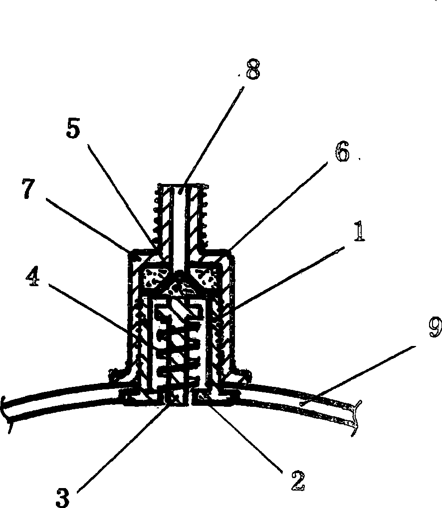
[0007] In the figure: the air-intake pile 1 connected with the tire 9, the lower end of which is a round sill 2, the shaft rod 3 is inserted inside, the spring 4 is inserted outside, the upper part withstands the piston 5, the inflatable nut 7 is screwed into the air pile 1, and the inside is installed The washer 6 is in close contact with the piston 5, and the upper end of the inflation nut 7 has an inflation port 8.

[0008] When in use, the air pump rotates and locks the inflation port 8, inflates inwardly, and the air pressure rushes into the piston 5 that is open and close to the gasket 6, and the pressurized gas enters the tire 9. After the air is filled, the spring 4 of the shaft rod 3 coats upwards. Bouncing top piston 5 closes up the pressurized gas in the tire 9 with gasket tightly again.


PUM


Abstract

The invention provides a valve core pile. A shaft lever arranged in an air intake pile and connected with a tyre integrally is sleeved with a spring, the upper end of the shaft lever is provided with a piston, the exterior of the air intake pile is screwed with an inflated screw cap the top of which is provided with an inflation inlet, and the interior of the inflated screw cap is provided with a gasket sealed with the piston in the air intake pile. The valve core pile can completely block an air valve so as not to leak air after the tyre is inflated, and an inner core is quite convenient to assemble, disassemble and replace.

Description

Technical field [0001] The invention relates to an inflatable pile used for tires, in particular to a valve core pile. Background technique [0002] At present, there are many styles of valve core piles used in tires, but all of them have the problems of easy air leakage, inconvenient installation and inflation. Contents of the invention [0003] The invention provides a valve core pile, which has the characteristics of being very convenient to assemble, fold and inflate, and is not easy to leak air after use. [0004] The technical scheme adopted in the present invention is: the air intake pile on the tire is a straight-mouth type, a round dam is provided at the bottom, a shaft is mounted on the round dam, a spring is placed on the outer cover, and a softer spring is installed on the upper end of the shaft. The piston and the air pile can be connected with the tire as a whole. There is an inflatable nut on the jacket, and the top of it is the inflation port. There is a g...

Claims


Application Information

Patent Timeline
IPC IPC(8): F16K15/20
Inventor 张少龙
Owner 张少龙
Why Eureka
Try Eureka