Brake device for support roller of coil stripping car

A technology of brake device and idler roller, which is applied in the direction of winding strips, transportation and packaging, and brake types, etc. It can solve the problems of unwinding of the belt tail, the failure of the brake device, and wear and tear, and solve the phenomenon of partial load , to avoid the effect of equipment failure and accident

Inactive Publication Date: 2009-04-01
BAOSHAN IRON & STEEL CO LTD
View PDF0 Cites 7 Cited by
  • Summary
  • Abstract
  • Description
  • Claims
  • Application Information

AI Technical Summary

Problems solved by technology

[0006] 2). Due to the positioning deviation of the brake hydraulic cylinder body 1' and the installation error of the idler roller 8', the position of the hydraulic cylinder is often not in the center of the two idler rollers 8', so that the brake block 6' will exist after braking. certain skew, according to image 3 Shown is the analysis of the mechanical principle of the force on the piston rod 2′. In this case, the horizontal component force F on both sides of the brake block 6 1 , F 2 The unevenness of the size will also cause the piston rod 2' to produce lateral unbalanced load
[0007] The consequences caused by the lateral load of the piston rod 2' are: the root of the thread connecting the piston rod 2' and the fork 4' is often broken, resulting in damage to the brake device and failure, resulting in inaccurate positioning of the tail of the coil or even the tail of the coil. Unwinding; the sealing device of the hydraulic cylinder piston rod 2' and the flange 3' is often worn prematurely due to the unbalanced load of the piston rod 2', resulting in oil leakage from the oil cylinder; more seriously, because the brake device and the idler roller 8' Often in watery working conditions, the damage to the sealing of the hydraulic cylinder often causes water to enter the hydraulic cylinder until it enters the entire hydraulic system, resulting in the failure of the hydraulic system oil, and even causing serious consequences of corrosion and damage to other hydraulic components

Method used


Image

  • Brake device for support roller of coil stripping car
  • Brake device for support roller of coil stripping car
  • Brake device for support roller of coil stripping car

Examples


Embodiment Construction

[0065] In order to better understand the structure, function and effect of the present invention, the following preferred embodiments are now described in detail in conjunction with the accompanying drawings. The same reference numerals designate the same or similar components.

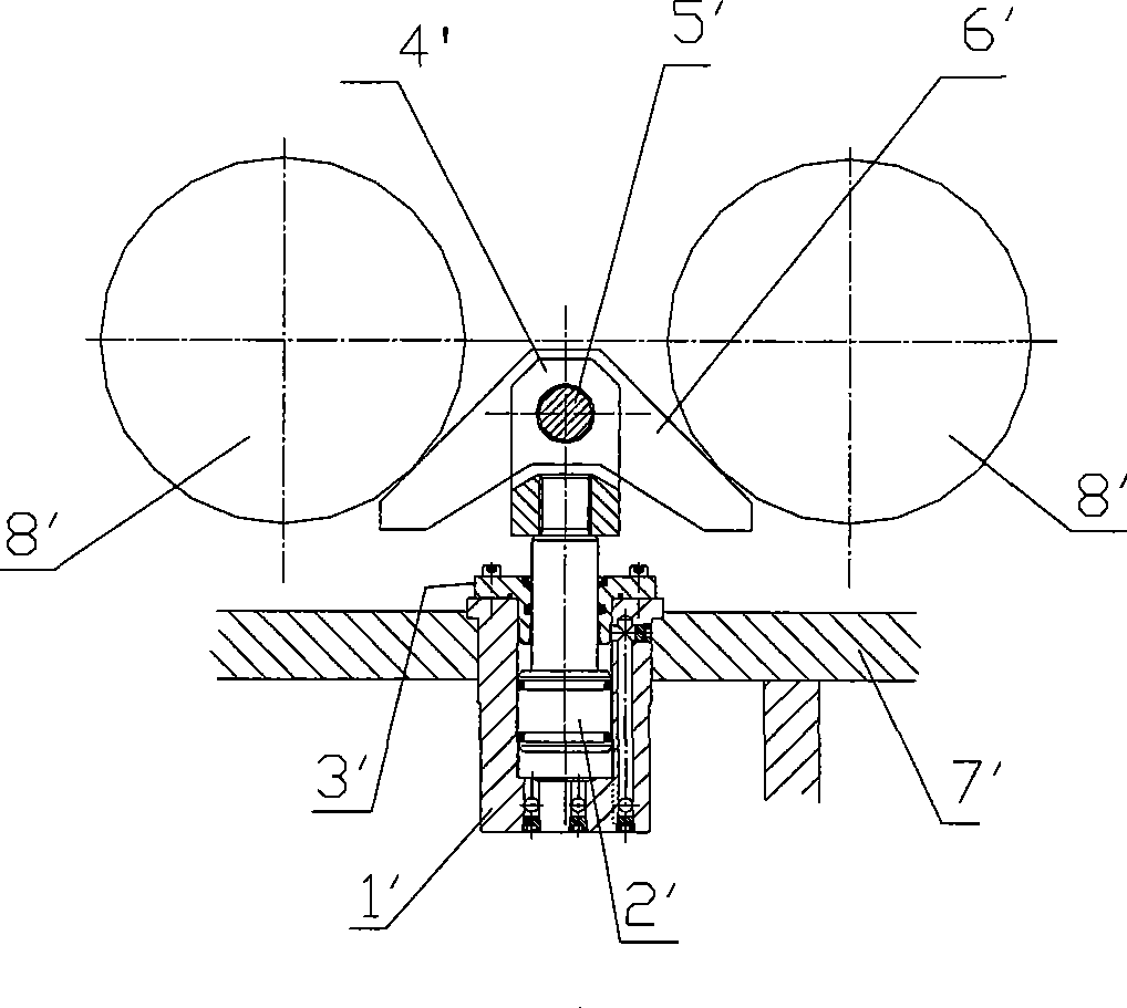
[0066] Figure 4 A top view of the assembly of the improved braking device according to the present invention is shown. The brake device mainly includes a hydraulic cylinder (not shown in the figure), a bracket 1, an ear seat 2, a brake arm 3 and a stop yoke 5, and the following details refer to Figure 5-7 Each component of this braking device is described in detail.

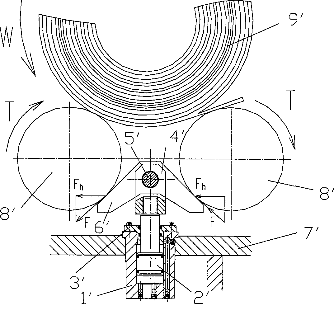
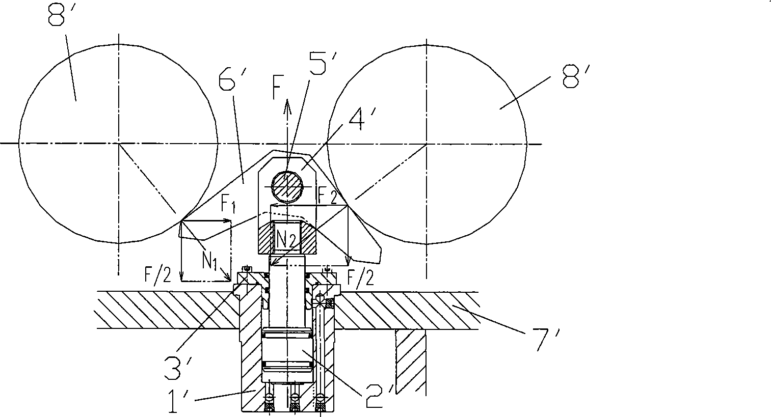
[0067] see first Figure 5 and Figure 6 , in this preferred brake device, the connecting shaft and the support in the adaptive floating system of the present invention are specifically a pair of trunnions 6 added on the hydraulic cylinder block 1' and a bushing 7 embedded in the inner hole. The ear seat 2, wherein the trunnion 6 ...


PUM


Abstract

The invention provides a supporting roller brake device used for a coil stripping trolley, comprising a hydraulic cylinder, a fork head and a brake part; wherein, the brake part comprises an inclined wedge block and a pair of brake arms which are pivotally and rotatablely connected with the fork head; each brake arm is pivotally and rotatablely connected with a bracket which is fixed on the supporting frame of the trolley respectively; the supporting roller brake device also comprises a self-adaptive floating system which is arranged between the hydraulic cylinder and the supporting frame of the trolley and comprises a pair of connecting shafts and a pair of supporters; each connecting shaft is respectively connected with one side of the hydraulic cylinder; each supporter is respectively connected with the supporting frame of the trolley; the connecting shafts are pivotally and rotatablely connected in the holes arranged on the supporters correspondingly. According to corresponding mechanic principle, the invention reconstructs the whole assembly and local assembly of the supporting roller brake device system. The novel supporting roller brake device of the coiling stripping trolley effectively solves the offset load phenomenon of the piston rod of the hydraulic cylinder and avoids a series of equipment failure and accidents caused by the offset loads.

Description

technical field [0001] The invention relates to the field of conveying hot-rolled thin-plate steel coils, in particular to an idler brake device in a coil unloading trolley device for steel coils. Background technique [0002] The function of the supporting roller in the unloading trolley device is to support the steel coil coiled from the strip steel. When the coiling is completed, the supporting roller has automatically risen to the set position and pressed against the tail of the strip coil. At this time, the supporting roller The roller brake device brakes the supporting roller, so as to avoid unwinding caused by disengaging the roller due to the inaccurate stop position of the tail of the coil due to the rotation of the supporting roller after the trolley unloads the coil. [0003] Existing idler brake devices such as figure 1 As shown, it includes a hydraulic cylinder, a fork 4' and a brake block 6', wherein the hydraulic cylinder is composed of a cylinder body 1', a ...

Claims


Application Information

Patent Timeline
Patent Type & Authority Applications(China)
IPC IPC(8): B65H19/22F16D49/00B21C47/24
Inventor 冯铁贾铭华乐建军陈铀童伟强李文辉
Owner BAOSHAN IRON & STEEL CO LTD
Why Eureka
Try Eureka