Method for restraining flow separation in transition section by utilizing guide vane

A technology of guide vanes and transition sections, which is applied in the field of using guide vanes to suppress flow separation in the transition section, and can solve problems such as increasing system complexity and increasing engine weight

Inactive Publication Date: 2009-05-06
廊坊智驰动力科技有限公司
View PDF0 Cites 7 Cited by
  • Summary
  • Abstract
  • Description
  • Claims
  • Application Information

AI Technical Summary

Problems solved by technology

This approach introduces additional losses while suppressing flow separation in the transition sect...

Method used


Image

  • Method for restraining flow separation in transition section by utilizing guide vane
  • Method for restraining flow separation in transition section by utilizing guide vane
  • Method for restraining flow separation in transition section by utilizing guide vane

Examples


Embodiment Construction

[0014] In order to describe the present invention more clearly, this specific embodiment takes a method for suppressing flow separation in a transition section as an example, and further illustrates the present invention with reference to the accompanying drawings.

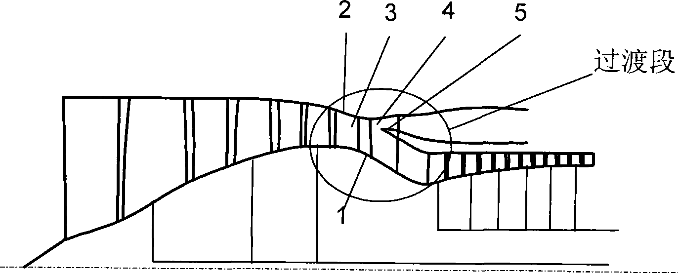
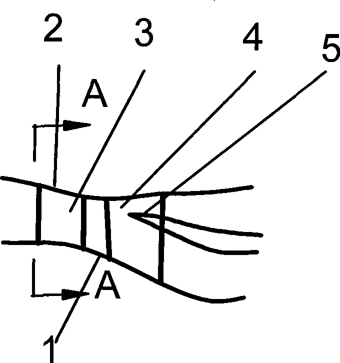
[0015] The first is to determine the installation position of the guide vane. In this example, the transition section structure see figure 2 , the total length of the transition section is 0.35m, and the axial chord length of the guide vane is 0.06m. The maximum curvature of the first bend of the transition section is located at 0.064m from the entrance of the transition section, making it 0.6 times the axial chord length from the leading edge of the guide vane, and the leading edge of the guide vane is located at 0.04m from the entrance of the transition section Position, the trailing edge is located 0.1m away from the entrance of the transition section.

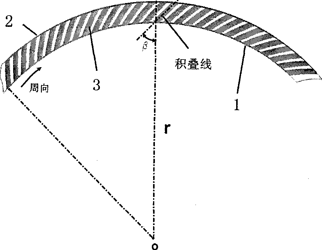
[0016] The second is to determine the angle between th...


PUM


Abstract

The invention relates to a method for inhibiting flow separation in a transition section of a compression system of an engine of a low-bypass aerial turbofan by using a guide vane. The method comprises the following steps: placing the guide vane at a first curved conduit on the inner wall of a transition section of an air compressor, and forming a vane force with gradient opposite to that of the prior pressure at the curved conduit of the transition section through changing a peripheral included angle of a laminated line and a radial line of the guide vane, so as to reduce pressure gradient of the flow direction at the curved conduit, and inhibit the flow separation in the transition section. Because the method can inhibit the flow separation in the transition section, the method can increase bending degree of the transition section, so as to reduce the length of the transition section. At the same time, because the guide vane is placed in the transition section, the method saves space occupied by the prior guide vane, and is favorable for reducing the length of the whole air compressor. The length of the transition section is estimated to be shortened by about 20 percent by adopting the method and the method contributes to the thrust mass ratio of the engine by about 1 percent.

Description

technical field [0001] The invention discloses a method for suppressing flow separation in a transition section of a small bypass ratio aviation turbofan engine compression system by using a guide vane. The invention can effectively reduce the length of the transition section between the aeroengine fan and the high-pressure compressor. Background technique [0002] The turbofan engine is the mainstream of modern aeroengines, and the small bypass ratio turbofan engine is the mainstream of military engines. And there is a transition section between the fan outlet and the high-pressure inlet of almost all small bypass ratio turbofans. With the gradual increase in the requirements for the thrust-to-weight ratio of aero-engines. Reducing the length of the transition section can effectively improve the compactness of the turbofan engine and increase its thrust-to-weight ratio. [0003] In recent years, the transition section of the turbofan engine has attracted everyone's attent...

Claims


Application Information

Patent Timeline
IPC IPC(8): F02K3/04
Inventor 李绍斌侯安平阙晓斌陆亚钧周盛
Owner 廊坊智驰动力科技有限公司
Why Eureka
Try Eureka