Supercharge Your Innovation With Domain-Expert AI Agents!

Steel bridge folding temporary locking method

A temporary locking, rigid-frame bridge technology, applied in bridges, bridge construction, erection/assembly of bridges, etc., can solve the problem of high engineering cost

Active Publication Date: 2010-09-15
CHINA RAILWAY MAJOR BRIDGE ENG GRP CO LTD
View PDF0 Cites 0 Cited by
  • Summary
  • Abstract
  • Description
  • Claims
  • Application Information

AI Technical Summary

Problems solved by technology

[0003] The technical problem to be solved by the present invention is to solve the problem of high engineering cost during the construction process of the rigid frame bridge

Method used


Image

  • Steel bridge folding temporary locking method
  • Steel bridge folding temporary locking method
  • Steel bridge folding temporary locking method

Examples


Embodiment Construction

[0017] The present invention will be described in detail below in conjunction with the accompanying drawings.

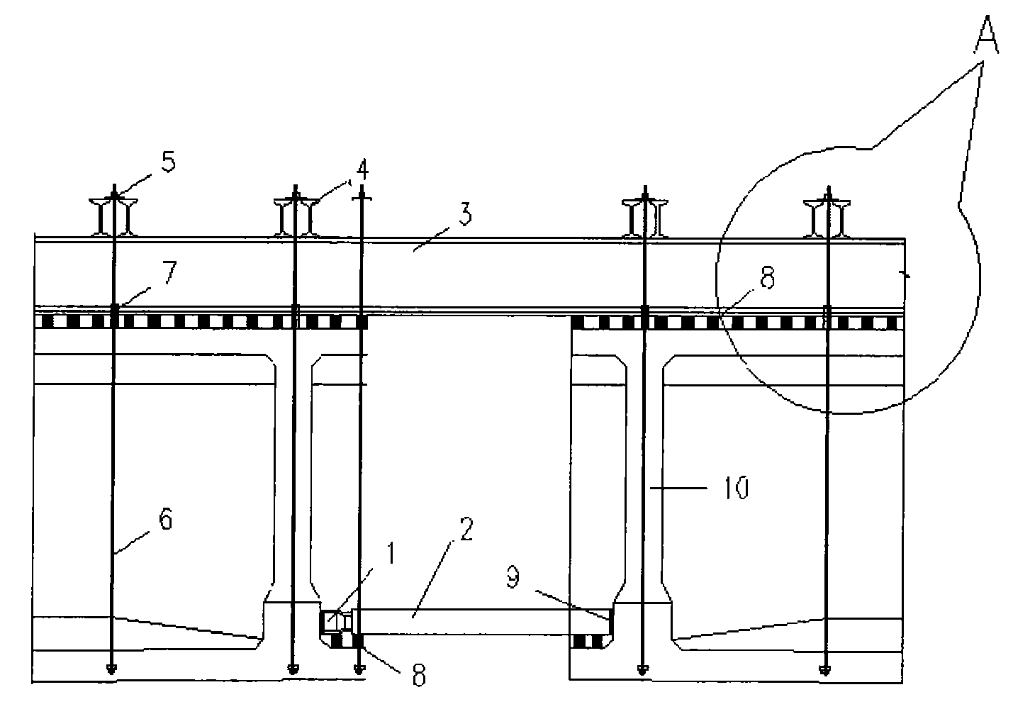
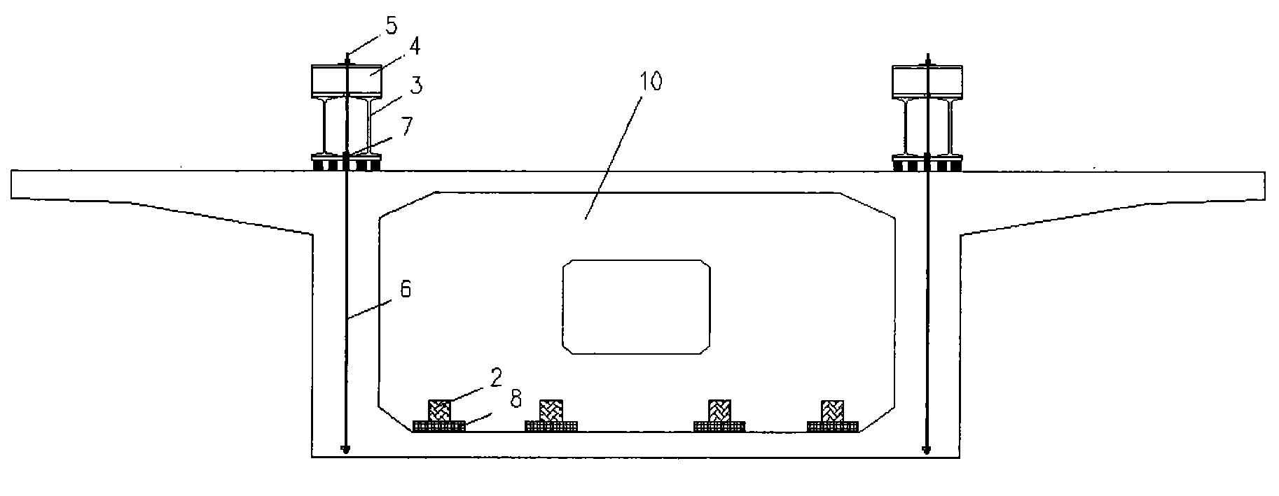
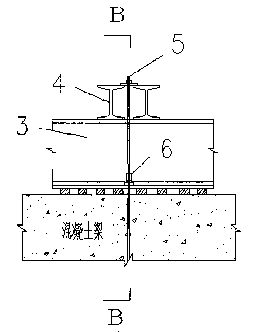
[0018] Such as Figure 1 to Figure 4 As shown, the present invention provides a kind of rigid frame bridge closing temporary locking method, comprises the following steps:

[0019] A. After the cantilever construction of the rigid-frame bridge is completed, place eight pads 8 on the upper surface of the box girder floor of the two cantilever end segments of each mid-span on the left and right sides of the closing mouth and level them, respectively on the left and right sides. A connecting rod 2 is placed on the pad 8 opposite to the box girder and a jack 1 is set between one end of the connecting rod 2 and the web of the box girder;

[0020] Evenly apply force to each jack 1, and ensure that the piston elongation of the four jacks 1 is basically the same during the loading process, so that the opening of the closing opening meets the required distance, and the dista...


PUM


Abstract

The invention relates to the field of the assembly of bridge construction engineering, in particular to a temporary locking method of the assembly of a rigid frame bridge, comprising the following steps: A. a plurality of jacks are respectively arranged on the upper surfaces of box girder soleplates at the left and the right sides of an assembly port, and connecting rods are arranged between the jacks and box girder web plates; B. force is uniformly applied to all the jacks so as to cause the assembly port to raise for the distance in accordance with the calculation requirement; C. a group oftrack girders are arranged on the upper surfaces of the left and the right box girders; D. anchor beams are arranged on the track girders and are connected into whole with main girder precision rolling screwed reinforcement by a reinforcement connector respectively by using a plurality of precision rolling screwed reinforcements; and E. each precision rolling screwed reinforcement is respectivelystretched with certain tonnage initial tension so as to cause the whole system to form a rigid skeleton. The method has the advantages that the whole process does not need welding, the construction procedure is simple and the construction period is shortened; furthermore, secondary processing is not needed for the section steel, and the section steel can be repeatedly used, thus saving cost.

Description

technical field [0001] The invention relates to the field of closure of bridge construction engineering, in particular to a temporary locking method for closure of a rigid frame bridge. Background technique [0002] At present, the temporary locking of rigid frame bridge closing construction is often realized by welding section steel as the rigid skeleton. This traditional method is often time-consuming and labor-intensive due to the on-site welding process. And because of the diversity of bridge projects, the section steel after secondary processing often cannot be effectively reused, thereby increasing the project cost. Contents of the invention [0003] The technical problem to be solved by the invention is to solve the problem of high engineering cost during the closing construction of the rigid frame bridge. [0004] In order to solve the above technical problems, the technical solution adopted in the present invention is to provide a temporary locking method for cl...

Claims


Application Information

Patent Timeline
Patent Type & Authority Patents(China)
IPC IPC(8): E01D21/00
Inventor 秦顺全李军堂涂满明毛伟琦张爱花周超舟江涌刘翠云祝文光
Owner CHINA RAILWAY MAJOR BRIDGE ENG GRP CO LTD
Features
  • R&D
  • Intellectual Property
  • Life Sciences
  • Materials
  • Tech Scout
  • Unparalleled Data Quality
  • Higher Quality Content
  • 60% Fewer Hallucinations
Learn More