Continuously adjustable mechanical hydraulic valve lift device

A gas valve lift, mechanical hydraulic technology, applied in valve devices, non-mechanically actuated valves, mechanical equipment, etc., can solve the problems of too many followers, the inability to control the valve opening time, and complex processing. Achieve the effect of improving economy, reducing pumping loss and increasing charge coefficient

Inactive Publication Date: 2009-06-03
SHANGHAI JIAO TONG UNIV
View PDF2 Cites 13 Cited by
  • Summary
  • Abstract
  • Description
  • Claims
  • Application Information

AI Technical Summary

Problems solved by technology

The patent application number is 200610069982.5, the publication number is CN 1959072A, and the name is an invention patent of an electro-hydraulic controlled internal combustion engine continuously variable valve timing system. Valve opening timing control
The patent application number is 200610169984.1, and the publication number is CN 101182807A. It is an invention patent named continuously variable valve lift device, which can adjust the valve lift and valve opening and closing duration at the same time, but obviously the processing is complicated and there are too many followers

Method used


Image

  • Continuously adjustable mechanical hydraulic valve lift device
  • Continuously adjustable mechanical hydraulic valve lift device
  • Continuously adjustable mechanical hydraulic valve lift device

Examples


Embodiment Construction

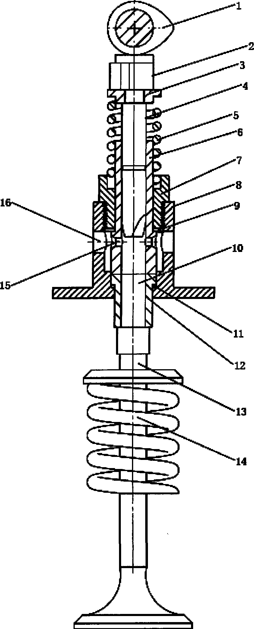
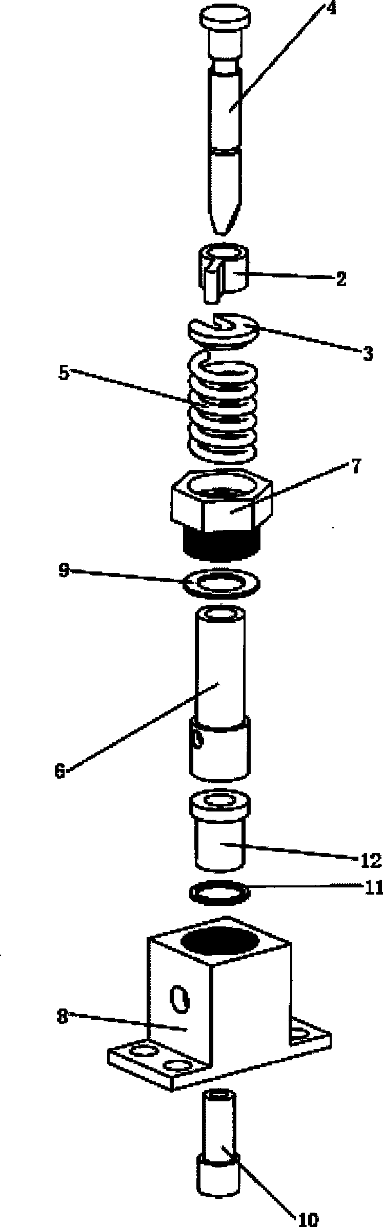
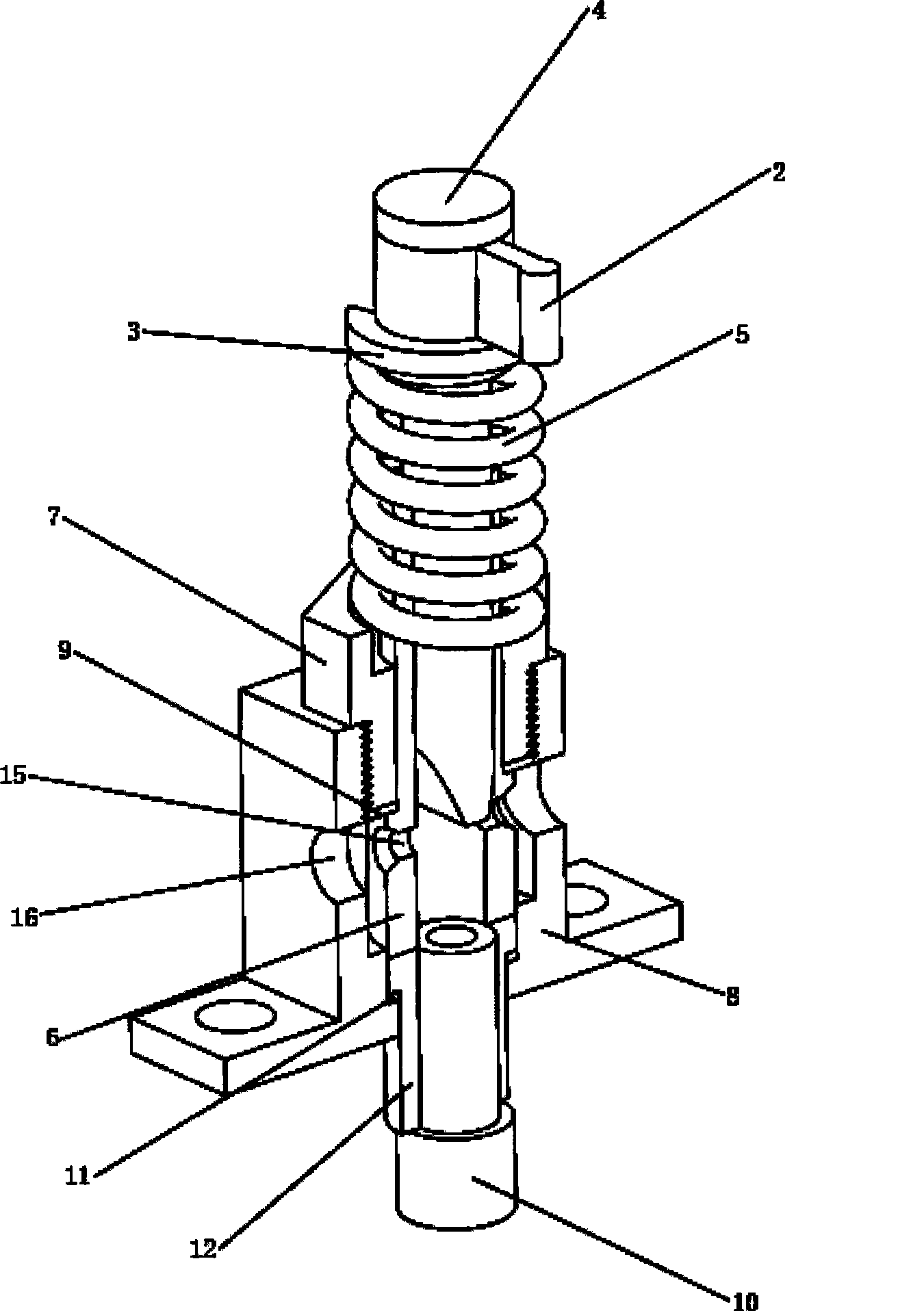
[0012] The specific implementation of the present invention will be further described below in conjunction with the accompanying drawings.

[0013] Such as figure 1 with figure 2 As shown, the present invention includes gas distribution cam 1, valve 13, valve spring 14, plunger adjustment arm 2, plunger spring seat 3, tappet plunger 4, plunger spring 5, tappet plunger sleeve 6, locking Nut 7, low-pressure oil cylinder 8, first gasket 9, execution plunger 10, second gasket 11, execution plunger sleeve 12; plunger adjustment arm 2 is installed on the shaft shoulder of tappet plunger 4, and The plunger 4 is interference fit, and the tappet plunger 4 is directly driven by the gas distribution cam 1; the head of the tappet plunger 4 has two oblique sections that are symmetrical along the axis, and its symmetry plane is the same as that of the plunger adjustment arm 2 along the axis. The plane of symmetry coincides; the plunger spring seat 3 is installed close to the bottom surfa...


PUM


Abstract

The invention relates to a continuously adjustable mechanical hydraulic valve lift device which belongs to the technical field of internal combustion engine. The continuously adjustable mechanical hydraulic valve lift device comprises a valve cam, a valve, a valve spring, a plunger piston adjusting arm, a plunger piston spring base, a tappet plunger piston, a plunger piston spring, a tappet plunger barrel, a retaining nut, a low pressure oil cylinder, a first gasket, a second gasket, an executing plunger piston and an executing plunger barrel. The lift range is decided by the relative position of the tappet plunger piston and a first oil hole at the tappet plunger barrel. The symmetrical plane of the plunger piston adjusting arm is coincident with the symmetrical plane of a diclinic section at the head of the tappet plunger piston, and the symmetrical plane of the plunger piston adjusting arm along the axial line is considered as a reference plane. When maximum lift is required, the plunger piston adjusting arm is rotated to ensure that the reference plane is parallel with the axial line of the first oil hole. When minimum lift is required, the plunger piston adjusting arm is rotated to ensure that the reference plane is vertical to the axial line of the first oil hole. When medium lift is required, the plunger piston adjusting arm is rotated to ensure that the reference plane and the axial line of the first oil hole form any angle between 0 to 90 degrees. The device has simple structure and can adjust valve lift, valve right timing and duration continuously.

Description

technical field [0001] The invention relates to an engine valve lift device, in particular to a continuously adjustable mechanical hydraulic valve lift device, which belongs to the technical field of internal combustion engines. Background technique [0002] In order to meet the requirements of environmental protection and sustainable development of human beings, energy saving and emission reduction are the development goals of today's automobile engines. The variable valve lift technology changes the charge of the mixed gas entering the cylinder by adjusting the valve timing or lift, so as to improve the power and fuel economy of the engine. [0003] The ideal valve timing and lift law should be adjusted in time according to the operating conditions of the engine, with sufficient flexibility. At low speed, use smaller valve overlap angle and smaller valve lift to prevent the fresh charge in the cylinder from flowing back into the intake system; at high speed, it should hav...

Claims


Application Information

Patent Timeline
Patent Type & Authority Applications(China)
IPC IPC(8): F01L1/34F01L9/02F01L13/00F01L9/12
Inventor 桂勇邓康耀崔毅石磊何方正
Owner SHANGHAI JIAO TONG UNIV
Why Eureka
Try Eureka