Large-powder low-torque pulsation permanent magnet synchronous motor for electro-spindle

A permanent magnet synchronous motor, torque pulsation technology, applied in synchronous machines, synchronous machine parts, electrical components, etc., can solve the problems of low machining accuracy, low motor efficiency, and low power density of induction motors, and improve constant power. Operating range, significant energy-saving effect, and effect of reducing torque ripple

Inactive Publication Date: 2009-09-09
HARBIN INST OF TECH
View PDF0 Cites 3 Cited by
  • Summary
  • Abstract
  • Description
  • Claims
  • Application Information

AI Technical Summary

Problems solved by technology

[0003] The invention proposes a high-power low-torque pulsating permanent magnet synchronous motor for electric spindles, which not only solves the complex structure of DC motors, difficult maintenance work and heavy workload, low motor efficiency, poor heat dissipation conditions, large moment of inertia, and dynamic The problem of poor performance solves the problems of low processing precision, low efficiency, low power density, large motor volume and low control precision of induction motors

Method used


Image

  • Large-powder low-torque pulsation permanent magnet synchronous motor for electro-spindle
  • Large-powder low-torque pulsation permanent magnet synchronous motor for electro-spindle

Examples


specific Embodiment approach 1

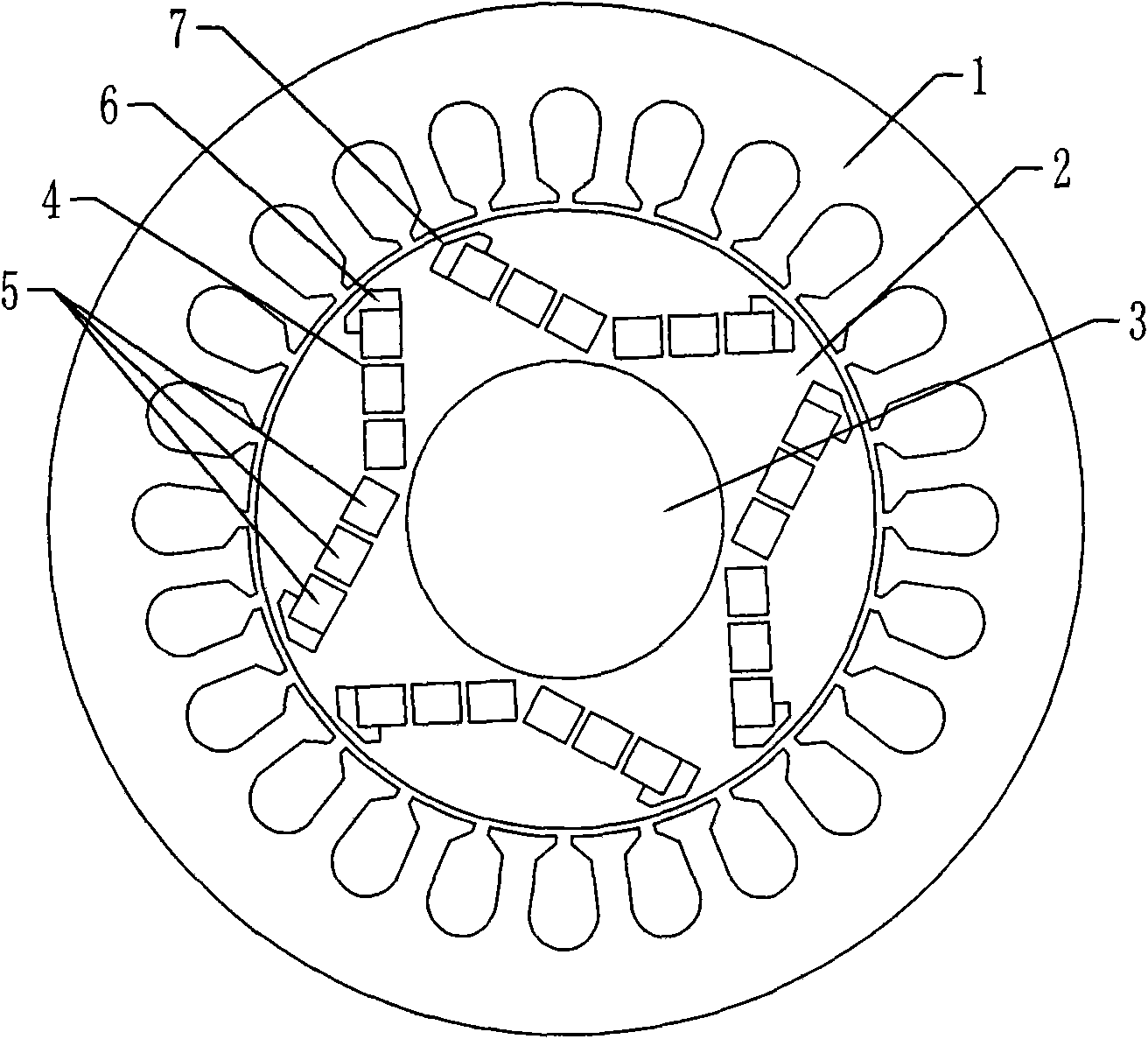
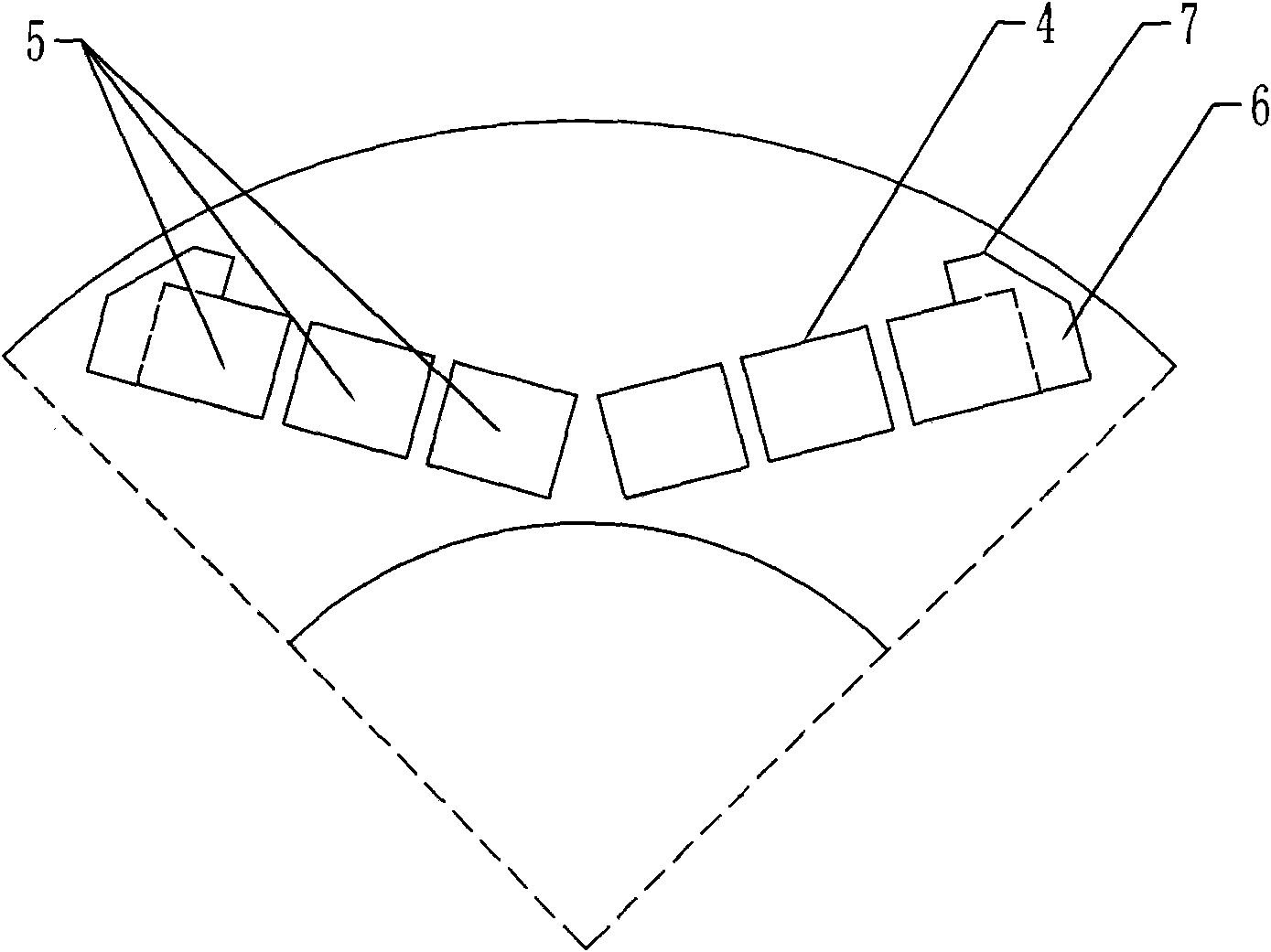
[0009] Specific implementation mode one: combine figure 1 and figure 2 Describe this embodiment, this embodiment is made up of stator 1, rotor, rotating shaft 3, permanent magnet and magnetic isolation bridge 6; Composed of permanent magnets with a rectangular cross-section; the end face of the rotor core 2 of the rotor is divided into 2P areas on average, and P is the number of pole pairs of the motor; 2n holes 4 with a rectangular cross-section are opened in each area along the axial direction of the rotor core 2 , n is a natural number; the 2n holes 4 of rectangular cross-section are arranged symmetrically along the center line of the end face of the rotor core 2 into a V-shaped or W-shaped opening facing the outer edge of the rotor core 2; such an arrangement can be made in a limited space More permanent magnets are placed inside to ensure that the permanent magnets provide sufficient effective magnetic flux. The cross-section of each group of segmented permanent magnet...

specific Embodiment approach 2

[0010] Specific implementation mode two: combination figure 2 This embodiment is described. The difference between this embodiment and the first embodiment is that the thickness between the magnetic isolation hole 7 and the outer edge of the rotor core 2 is 0.5mm-10mm. Other compositions and connection methods are the same as those in Embodiment 1.

specific Embodiment approach 3

[0011] Embodiment 3: The difference between this embodiment and Embodiment 1 is that the segmented permanent magnet group 5 adopts NdFeB permanent magnets as permanent magnets with a rectangular cross section. Other compositions and connection methods are the same as those in Embodiment 1. NdFeB permanent magnets have high coercivity and remanence.


PUM


Abstract

A large-powder low-torque pulsation permanent magnet synchronous motor for an electro-spindle is disclosed, relating to the field of motor and solving the problems of complex structure of the motor, low efficiency of the motor, inferior heat dissipation condition, large rotational inertia, poor dynamic property, low processing precision, low efficiency, low powder density, large volume of the motor and low control precision. A permanent magnet of the invention is a segmented permanent magnet set composed of 2n permanent magnets having rectangular cross sections; an end face of a rotor core is divided averagely into 2P areas, each of which is provided, in an axial direction, with 2n pores having the rectangular cross sections; along a circle center line of the end face of the rotor core, the pores are symmetrically arrayed in a V or W shape, an opening of which faces the outer edge of the rotor core; the permanent magnets are embedded in the pores; the width of a magnetic bridge is 0.5-L/2mm; two sides of the outer edge of the pores arrayed at the head and the tail of the V or W shape extend in the direction of the outer edge of the rotor core so as to form a magnetic isolation pore in which a non-magnetic conduction material is filled to form a magnetic isolation bridge. The invention weakens the vibration of the electro-spindle motor by virtue of the shape and the size of the magnetic isolation bridge.

Description

technical field [0001] The invention relates to the field of motors, in particular to a low-torque pulsating permanent magnet synchronous motor for a high-power, high-speed, high-precision turning and milling electric spindle. Background technique [0002] Spindle motors currently mainly include DC motors and induction motors, especially induction motors, which occupy a dominant position in the spindle drives of CNC machine tools and high-precision machine tools, but both of these two motors have some shortcomings. The structure of the DC motor is complex, the maintenance work is difficult and the workload is large, the motor efficiency is low, the heat dissipation condition is poor, the moment of inertia is large, and the dynamic performance is poor. Induction motors have the following problems: first, the rotor generates heat, especially at low speeds, and the temperature rise is serious, and the heat is directly transmitted to the spindle, which affects the machining accu...

Claims


Application Information

Patent Timeline
Patent Type & Authority Applications(China)
IPC IPC(8): H02K21/00H02K21/02
Inventor 李立毅曹继伟寇宝泉张亮亮
Owner HARBIN INST OF TECH
Why Eureka
Try Eureka