
Switch crowbar circuit and control method thereof
An arc-extinguishing circuit and arc-switching technology, which is applied to circuits, electrical switches, electrical components, etc., can solve problems such as unfavorable general use, unsatisfactory arc-extinguishing effect, and inability to achieve better arc-extinguishing effect, and achieves simple structure and guaranteed reliability, improved performance
- Summary
- Abstract
- Description
- Claims
- Application Information
AI Technical Summary
Problems solved by technology
Method used
Image

Examples
Embodiment 1
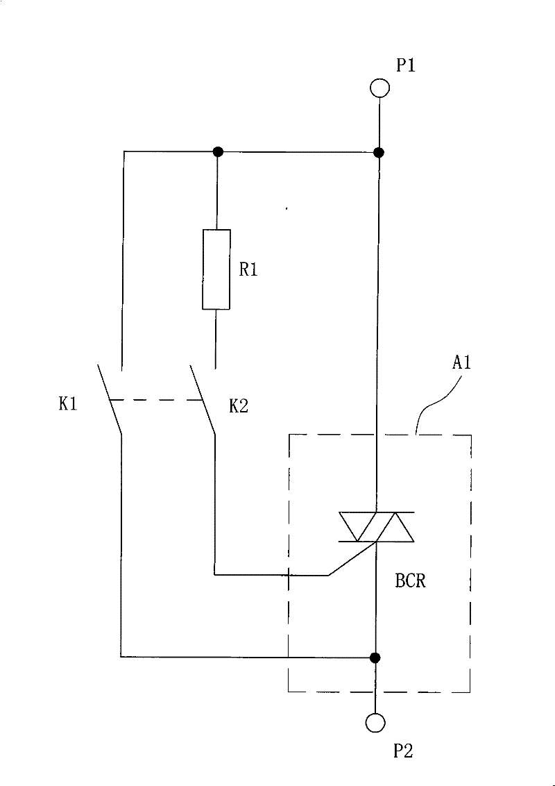
[0052] Embodiment one, such as image 3 Shown:
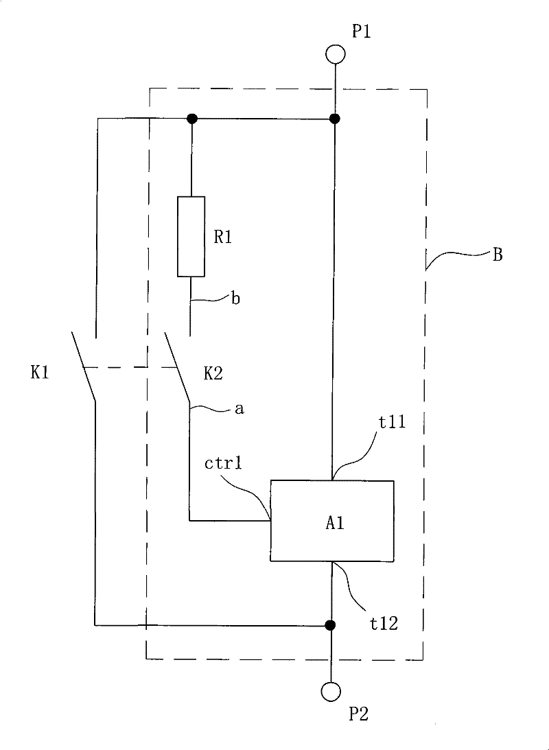
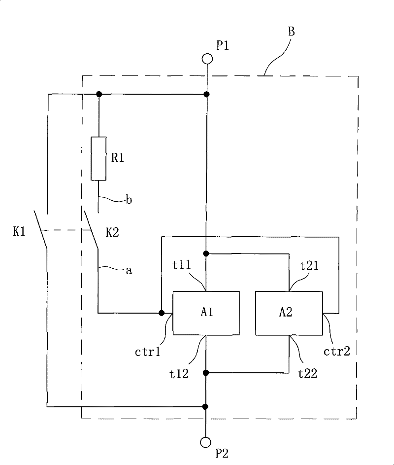
[0053] The arc suppression circuit specifically includes a main contact K1, an auxiliary contact K2, a current-limiting resistor R1 and a bidirectional thyristor BCR, wherein the main contact K1 has a first electrode terminal P1 and a second electrode terminal P2, which are bidirectionally controllable The anode of the silicon BCR is connected to the first electrode terminal P1 of the main contact K1, the cathode of the bidirectional thyristor BCR is connected to the second electrode terminal P2 of the main contact K1, and the control terminal of the bidirectional thyristor BCR is connected to the auxiliary contact K2 The first terminal a of the auxiliary contact K2 is connected to the first electrode terminal P1 of the main contact K1 through the current limiting resistor R1.
[0054] working principle:
[0055] Closing process: the auxiliary contact K2 is closed first, at this time, the control terminal of the bidirectional ...
Embodiment 2
[0058] Embodiment two, such as Figure 4 Shown:
[0059] The difference between this embodiment and Embodiment 1 is that the bidirectional thyristor BCR is replaced by two parallel-connected first one-way thyristor SCR1 and second one-way thyristor SCR2, wherein the first one-way thyristor SCR2 The anode of the silicon controlled rectifier SCR1 is connected to the first electrode terminal P1 of the main contact K1, the cathode of the first one-way thyristor SCR1 is connected to the second electrode terminal P2 of the main contact K1, and the first one-way thyristor SCR1 The control terminal is connected to the first terminal a of the auxiliary contact K2; the anode of the second one-way thyristor SCR2 is connected to the second electrode terminal P2 of the main contact K1, and the cathode of the second one-way thyristor SCR2 is connected to the main contact The first electrode terminal P1 of the head K1 is connected, and the control terminal of the second one-way thyristor SC...
Embodiment 3
[0061] Embodiment three, such as Figure 5 Shown:
[0062] The arc suppression circuit includes a main contact K1, an auxiliary contact K2, a current limiting resistor R1, a capacitor C, a time delay resistor R2, an NPN transistor BG, a first voltage regulator tube D1 and a second voltage regulator tube D2, wherein, The main contact K1 has a first electrode terminal P1 and a second electrode terminal P2. One way of the base of the triode BG is connected to the first terminal a of the auxiliary contact K2, and the other way is connected to the cathode of the first voltage regulator tube D1. The triode BG The emitter of the transistor is connected to the second electrode terminal P2 of the main contact K1, the collector of the triode BG is connected to one end of the delay resistor R2, and the other end of the delay resistor R2 is connected to the first terminal of the main contact K1 after passing through the capacitor C One electrode terminal P1 is connected, the collector of...
PUM
 Abstract
Description
Claims
Application Information