Bearing retainer and machining technique thereof

A bearing retainer and processing technology, used in bearing components, shafts and bearings, mechanical equipment, etc., can solve the problems of load capacity and working temperature limitations, low operating temperature, and high overall cost, and improve product accuracy and reliability. performance, avoid waste, and improve utilization

Inactive Publication Date: 2010-03-17
宁波达克轴承有限公司
View PDF0 Cites 23 Cited by
  • Summary
  • Abstract
  • Description
  • Claims
  • Application Information

AI Technical Summary

Problems solved by technology

[0003] The present invention is provided to solve the current situation that the existing bearing retainer is either greatly limited in bearing load capacity and operating temperature due to the nylon plastic structure, or the overall cost is relatively high due to the machining process retainer made of green brass material. A bearing retainer with simple structure, simple processing process, making full use of processing raw materials, improving processing efficiency, precision and pass rate
[0006] It not only solves the poor quality problems caused by the use of nylon material structural retainers, such as poor strength, low operating temperature, and easy aging; it also maximizes the utilization rate of the low-carbon steel plate itself to avoid unnecessary waste of materials Cost, compared with the general process scheme that adopts the overall blanking, multiple stretching, bottom cutting, and forming scheme, it reduces the waste of material cost, avoids the core block waste generated by bottom cutting, improves production efficiency, and avoids After multiple stretches, there is a certain difference in the overall thickness of the entire plate thickness.

Method used


Image

  • Bearing retainer and machining technique thereof
  • Bearing retainer and machining technique thereof
  • Bearing retainer and machining technique thereof

Examples


Embodiment Construction

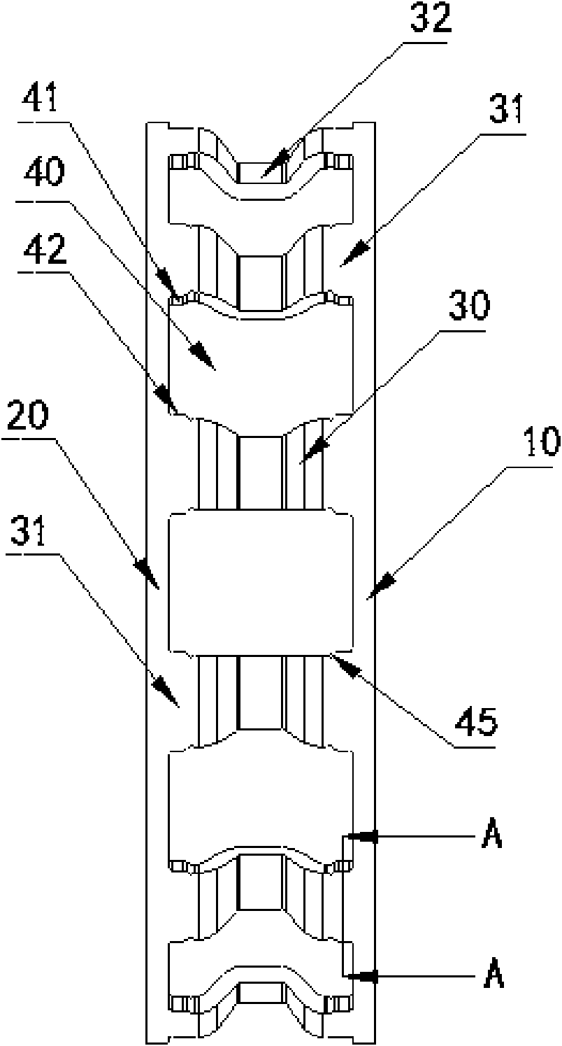
[0031] figure 1 In the illustrated embodiment, a processing technique for a bearing retainer is characterized in that it mainly includes the following steps

[0032] 1. Blanking: According to the required bearing capacity of the bearing to be processed, calculate the circumferential length and height of the retainer that needs to be processed to install the locking cylindrical roller, and punch the used low-carbon steel material according to the calculated size. Long strips that meet the circumferential length and height of the stamping holder;

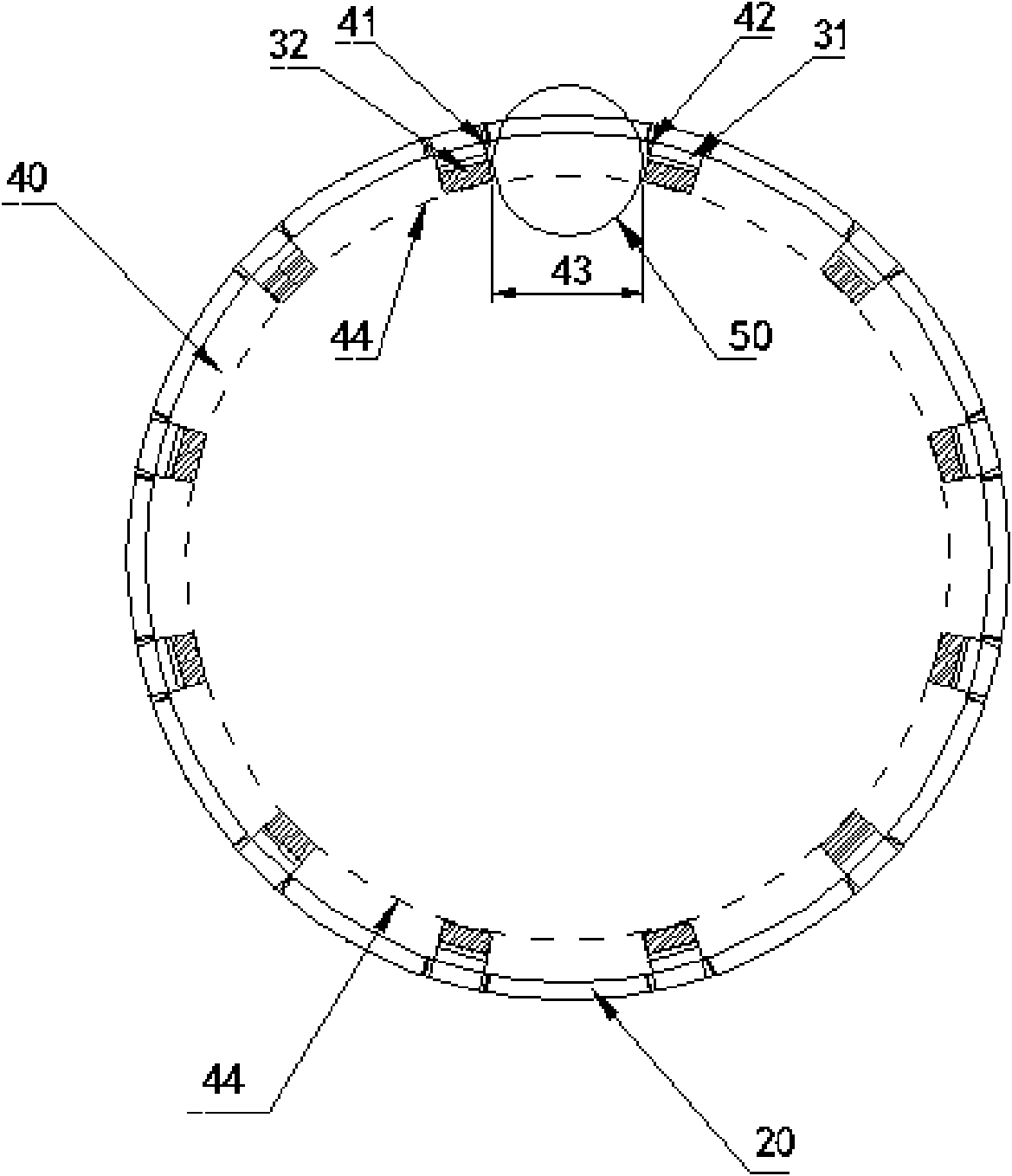
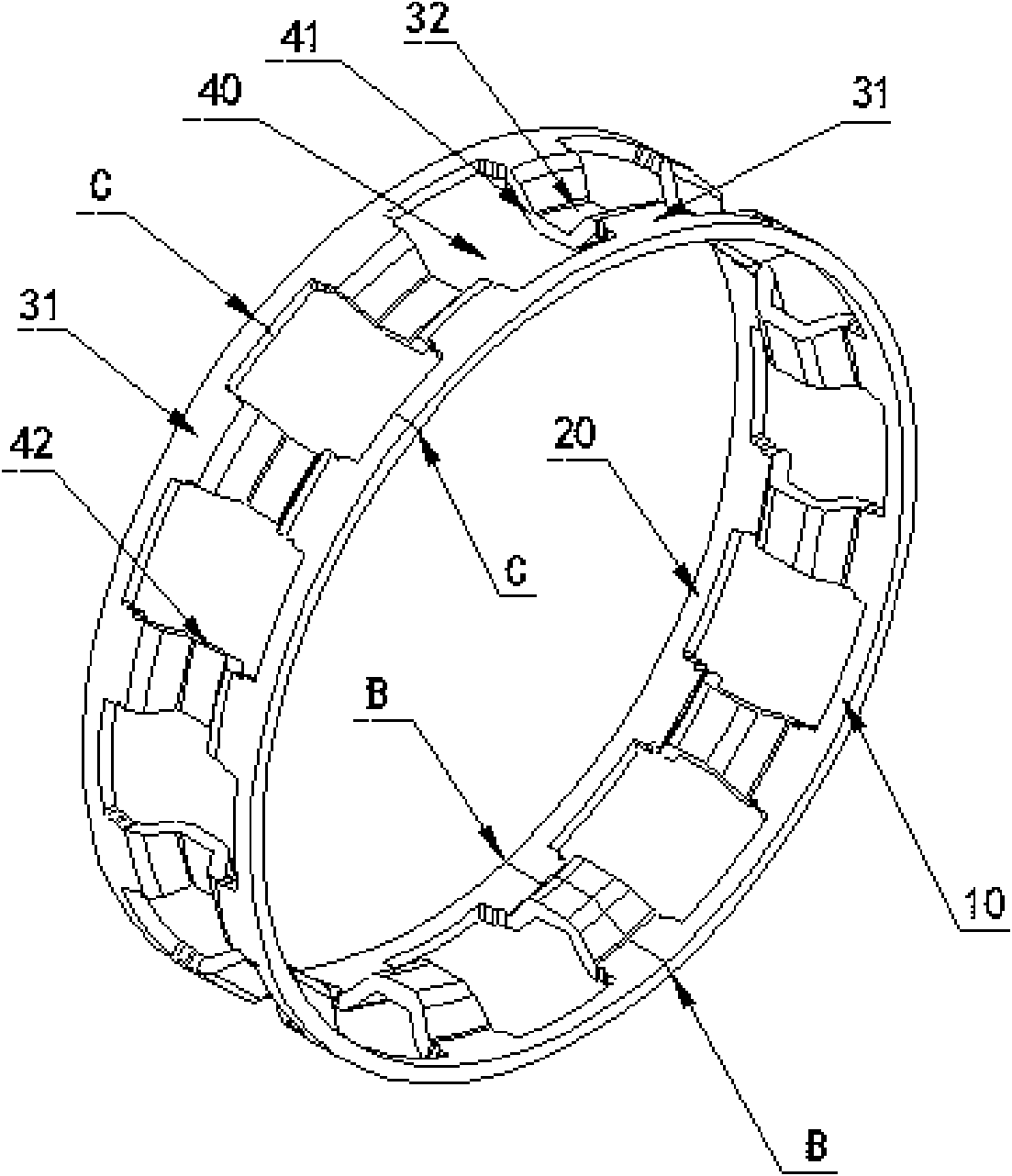
[0033] 2. Punch out all the pockets at one time: install and use the cylindrical roller size of the bearing according to the needs, and use the stamping die to punch out all the pockets that need to lock the cylindrical roller at one time. , Including the locking surface structure of punched pocket structure and its oblique slope structure;

[0034] 3. Stamp the groove structure of all pocket beams at one time: use a stamping die to punch a...


PUM


Abstract

The invention discloses a bearing retainer and a machining technique thereof. The technique mainly comprises: blanking perimeter and height required by the retainer at a time, moulding all cage pocketstructures of the retainer at a time, and punching all the cage pockets into concave cage beams provided with groove structures at a time; circling the retainer bracket with circling mould, and welding the butt ports of two ends of the circle to form an integral bearing retainer structure. The machined bearing retainer bracket is in the integral bearing retainer structure formed by manufacturinginner and outer ring beams, cage pockets, concave cage beams between adjacent cage pockets, and boundary beams for connecting the concave cage beams to the space between the inner and outer ring beamswith the same mild steel plate through the previous technique so that the invention has the advantages of reducing accumulated technique deviations, improving precision and reliablity of products, solving the problem of high cost of material waste in conventional bearing machining technique, fully increasing the utility rate of material, and further improving the production efficiency of the bearing retainer.

Description

Technical field [0001] The invention relates to a bearing retainer, in particular to a cylindrical roller bearing retainer and its processing technology. Background technique [0002] The bearing structure usually includes inner ring, outer ring, retainer and rolling elements. The function of the bearing retainer is to guide and drive the rolling elements to roll on the correct raceway; the bearing retainer also separates the rolling elements at equal distances and distributes them evenly. On the circumference of the track to prevent collision and friction between the rolling elements during work; the rolling element structure includes balls and cylindrical rollers, and the cylindrical roller bearing retainer structure and technology in the cylindrical roller bearing technology can be divided into nylon A retainer composed of injection-molded cylindrical rollers and cast blue, brass or steel bars that are processed into a cylindrical shape and stamped copper cover plates or steel...

Claims


Application Information

Patent Timeline
Patent Type & Authority Applications(China)
IPC IPC(8): F16C33/46B21D22/00
Inventor 梁晓东
Owner 宁波达克轴承有限公司
Why Eureka
Try Eureka