Coaxial constant force spring support hanger

A constant force spring, coaxial technology, applied in the field of supports and hangers, can solve the problems of blocking, locking and unlocking of the locking device of the middle support and hanger, and difficulty in processing and generation, and achieve symmetrical force and simple locking and unlocking , low cost effect

Inactive Publication Date: 2010-06-09
高永峰
View PDF2 Cites 8 Cited by
  • Summary
  • Abstract
  • Description
  • Claims
  • Application Information

AI Technical Summary

Problems solved by technology

This makes the processing of this support and hanger more difficult and costly; second, this support and hanger is equipped with two auxiliary springs in the horizontal direction, which makes its lateral dimension larger and difficult to arrange in places with limited space ; Third, when multiple supports and hangers are used in parallel, the locking device of the middle support and hanger may be blocked, making it difficult to lock and unlock

Method used


Image

  • Coaxial constant force spring support hanger
  • Coaxial constant force spring support hanger
  • Coaxial constant force spring support hanger

Examples


Embodiment 1

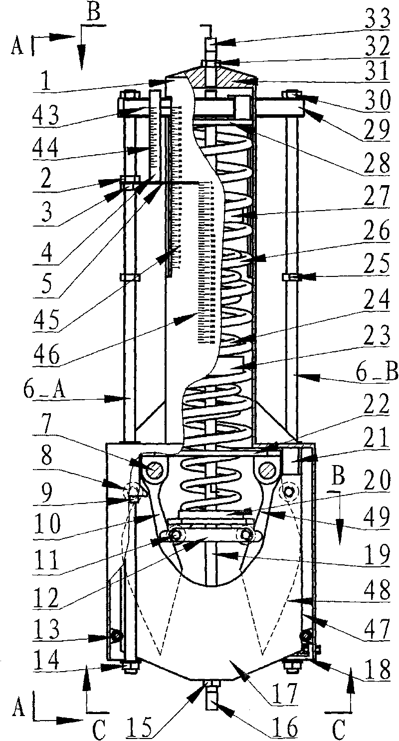
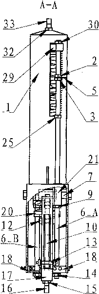
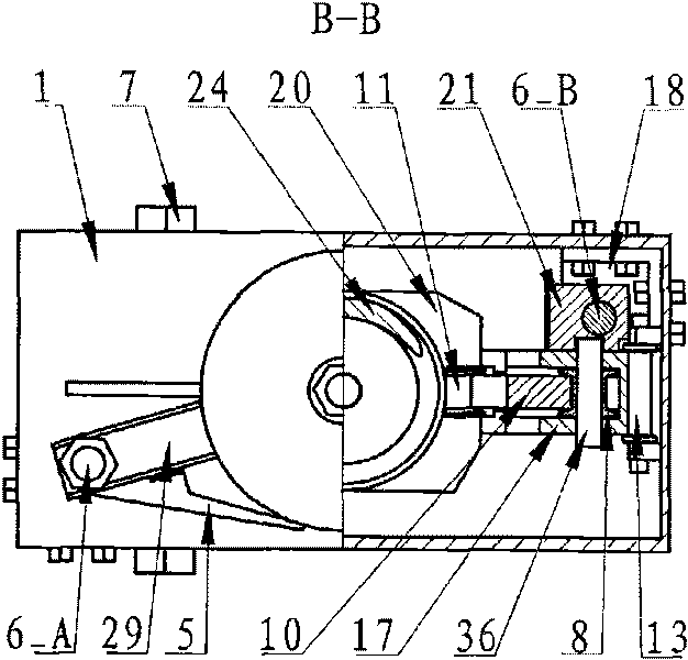
[0046] Such as figure 1 , 2 , 3, 4, and 5, the present embodiment includes housing 1, upper compression nut 2, lower compression nut 3, scale 4, pointer 5, left threaded rod 6_A, right threaded rod 6_B, camshaft 7, outer roller 8. Compression nut 9, cam 10, inner roller 11, roller connecting rod 12, guide wheel 13, lower lock nut 14, compression nut 15, lower boom 16, inner frame 17, locking support plate 18, pull rod 19, Inner spring lower end cap 20, nut 21, outer spring lower end cap 22, spacer ring 23, inner spring 24, upper lock nut 25, outer spring 26, inner spring upper end cap 27, outer spring upper end cap 28, adjustment beam 29, adjustment nut 30, the upper connection nut 31, the compression nut 32, the upper boom 33, the lower connection nut 34, the compression nut 35, the roller shaft 36, the compression nut 37.

[0047] In this embodiment, the shell 1 is welded by the upper cylinder and the lower rectangular box-shaped structure. The boxed structure is welded by...

Embodiment 2

[0053] Such as Figure 6 As shown, the basic composition and working principle of this embodiment are the same as those of Embodiment 1, the main difference is that the supporting method is seat hanging type, that is, the housing 1 is not suspended on the external support structure, but is fixed on the The two supports 39 of the shell 1 are supported on the external support structure 40 , and the inner frame 17 is connected to the pipeline and the equipment 38 through the lower suspension rod 16 and the compression nut 15 .

Embodiment 3

[0055] Such as Figure 7 As shown, the basic composition and working principle of this embodiment are the same as those of Embodiment 1, the difference is that in this embodiment, three support hangers are connected in parallel, the upper part shares a pull-up plate 41 and is connected with the external support structure, and the lower part shares a A drop plate 42 is connected to the piping and equipment 38 .


PUM


Abstract

The invention relates to a coaxial constant force spring support hanger which mainly comprises a shell, an inner frame, cams, an inner spring, an outer spring, a spring end cover, a threaded rod and inner and outer roller wheels, wherein the inner and outer springs and a pull rod fixedly connected on the inner frame are coaxial; the respective upper end cover of the inner and outer springs is fixedly connected with the inner frame; and the lower end cover of the outer spring is fixedly connected with the shell. The two cams are symmetrically articulated on the shell, and the working curves of the inner and outer cams are respectively matched with the inner and outer roller wheels arranged on the inner frame and the lower end cover of the inner spring. The threaded rod fixedly connected on the inner frame is provided with an adjusting, locking and indicating device. The invention can be used for hangers of pipelines with cold and thermal walking in power industry, petrochemical industry and the like and occasions of contact screen wires and the like of electrified railways, needing constant tensile force.

Description

technical field [0001] The invention relates to a support and hanger, in particular to a coaxial constant force spring support and hanger for various pipelines with cold and heat displacement. Background technique [0002] At present, in order to reduce the additional stress caused by thermal expansion and contraction of pipelines, two kinds of constant force spring supports and hangers are widely used in electric power, petrochemical and other industries: connecting rod type and main and auxiliary type. [0003] The application number is 87207385, and the Chinese patent entitled "Constant Force Spring Hanger" shows a connecting rod type constant force spring hanger. The spring support and hanger is based on the principle of moment balance, and the main components are the rotary frame, the fixed frame, and the spring. Wherein, the fixed frame is hinged with the revolving frame by a shaft, and the revolving frame is connected with the spring through the pull plate and the pu...

Claims


Application Information

Patent Timeline
Patent Type & Authority Applications(China)
IPC IPC(8): F16L3/20
Inventor 高永峰张相炎刘宁
Owner 高永峰
Why Eureka
Try Eureka